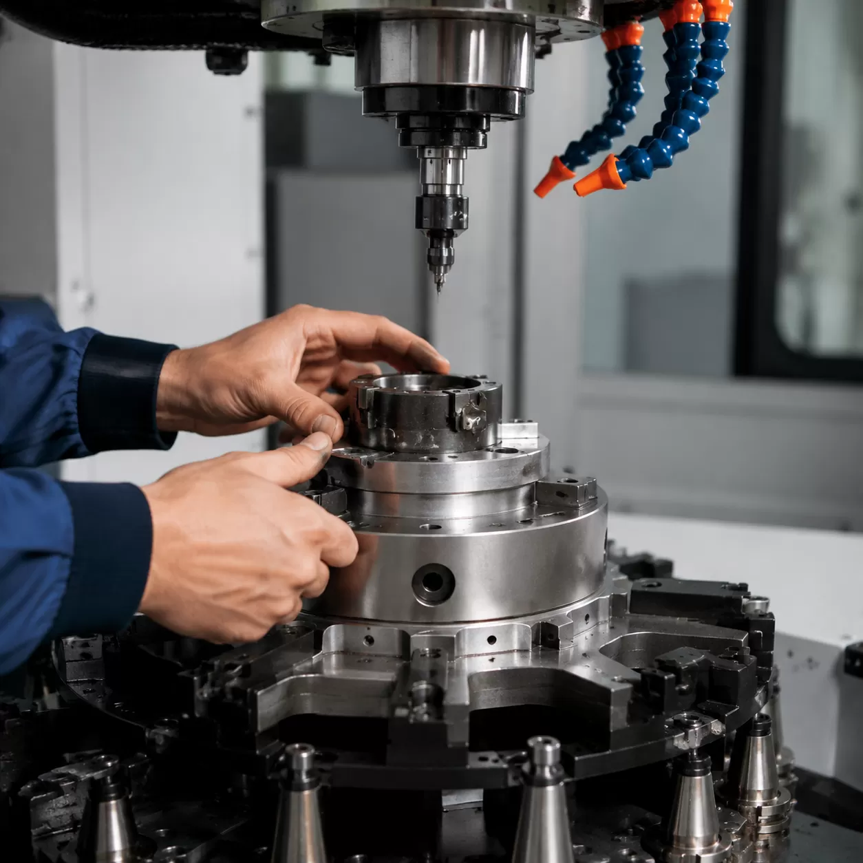
The traditional bottleneck of stopping production, reaching for dual wrenches, and manually breaking open collet nuts to swap a bit is a massive drain on efficiency. In high-output manufacturing, manual tool changes introduce shop-floor friction that eats into profit margins.
To eliminate this waste, we design our machinery around the automatic tool changer (ATC) chuck—a dynamic electromechanical system that integrates mechanics, pneumatics, and digital controls to swap tools automatically. By automating this single transition, a CNC wood router can switch from a nesting bit to a profile cutter in seconds without human intervention.
Impact on Non-Productive Cycle Time
Transitioning from manual swapping to an ATC system completely redefines your workflow efficiency.
- Manual Swap: 60 to 180 seconds per tool change (requires stopping the spindle, manual wrench clearing, bit adjustment, and manual Z-axis re-zeroing).
- ATC Swap: 3 to 8 seconds per tool change (fully automated, precise, and executed on the fly).
Translating these saved seconds across hundreds of tool swaps per shift results in significant reductions in non-productive cycle times. This increased uptime allows our global partners to boost daily sheet volume, minimize operator fatigue, and maintain a highly competitive edge in the automated woodworking market.
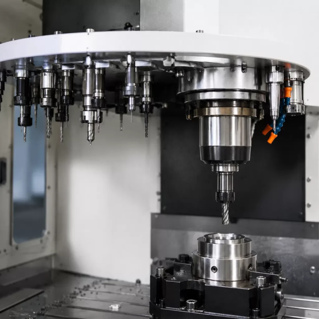
Inside a High-Speed Tooling Automation Spindle
Achieving flawless, high-speed automated production requires an inside look at how a CNC ATC chuck works under the hood. The magic relies on an exact mechanical marriage between the tool holder and the machine spindle. Whether your machine runs an ISO20, BT30, or HSK tool holder taper, it is engineered to mate perfectly with the internal spindle taper. This precise physical connection ensures zero-runout performance, keeping your cuts perfectly true even at speeds exceeding 24,000 RPM.
Before any tool holder ever enters the storage magazine, the cutting bit must be secured tightly inside the collet nut assembly. Once loaded, the heavy-duty mechanics inside the spindle handle the rest.
The Locking Mechanism Components
The mechanical lock-in depends on a few critical internal components working together:
- Internal Spindle Drawbar Mechanism: A hardened steel shaft running down the center of the spindle that moves up and down to clamp or release the tool.
- Heavy-Duty Disc Springs: A stacked cluster of high-tension Belleville washers that constantly push the drawbar upward. This mechanical spring force provides the continuous, failsafe clamping energy.
- Pull Stud Engagement & Retention Knob: The upper knob of the tool holder (the pull stud) is gripped tightly by the drawbar’s internal metal fingers (collet claws).
The massive retention knob clamping force pulls the tool holder up into the taper with thousands of pounds of pressure. This extreme force ensures the cutting bit stays completely rigid and locked down, easily absorbing intense lateral loads during heavy nesting and high-feed routing operations.
How the Automatic Tool Changer Swaps Tools
Understanding how does cnc atc chuck work requires looking at the precise, automated choreography that happens every time a machine swaps bits. Instead of manual intervention, the system relies on a sequence of synchronized mechanical and pneumatic actions to keep production moving.
Phase 1: The CNC Controller Command
The entire process kicks off in the G-code program. When the machine hits an M06 code, the CNC controller halts the current cutting path and initiates the tool change sequence. The machine reads the specific tool number assigned next and directs the gantry to the exchange zone. If you are new to setup routines, learning how to program a cnc machine correctly ensures these tool codes are seamlessly integrated into your design files.
Phase 2: Spindle Braking and Dust Purge
Before any mechanical swapping occurs, the spindle brakes to a complete halt. It moves along the linear rails to the designated tool change position. Simultaneously, a spindle purge air blast activates. This blast of compressed air deflects wood dust, chips, and debris away from the mating surfaces, ensuring no contaminants get trapped inside the taper.
Phase 3: Actuating the Spindle Drawbar Mechanism
Once positioned, the machine activates a pneumatic release sensor and fires an internal pneumatic piston. This piston packs enough force to overcome the heavy-duty internal spring stack, pushing the spindle drawbar mechanism downward. This downward movement forces the clamping fingers to open up inside the spindle.
Phase 4: Depositing and Retrieving the Tool
With the mechanical grip relaxed, the automatic tool changer safely deposits the active tool holder into its slot in the tool magazine. The machine axes then shift slightly to align the empty spindle directly over the next required tool in the carousel or rack, ready for retrieval.
Phase 5: Achieving Massive Mechanical Lock-In
After the spindle lowers onto the new tool holder, the pneumatic air pressure is instantly released. Without the air pressure fighting it, the internal disc spring stack snaps back upward with massive mechanical force. This high-tension retraction pulls the pull stud engagement tight, locking the tool holder taper securely into the spindle with thousands of pounds of retention knob clamping force, ready for high-speed cutting.
Rotary Carousel Magazines vs. Linear Rack Tools
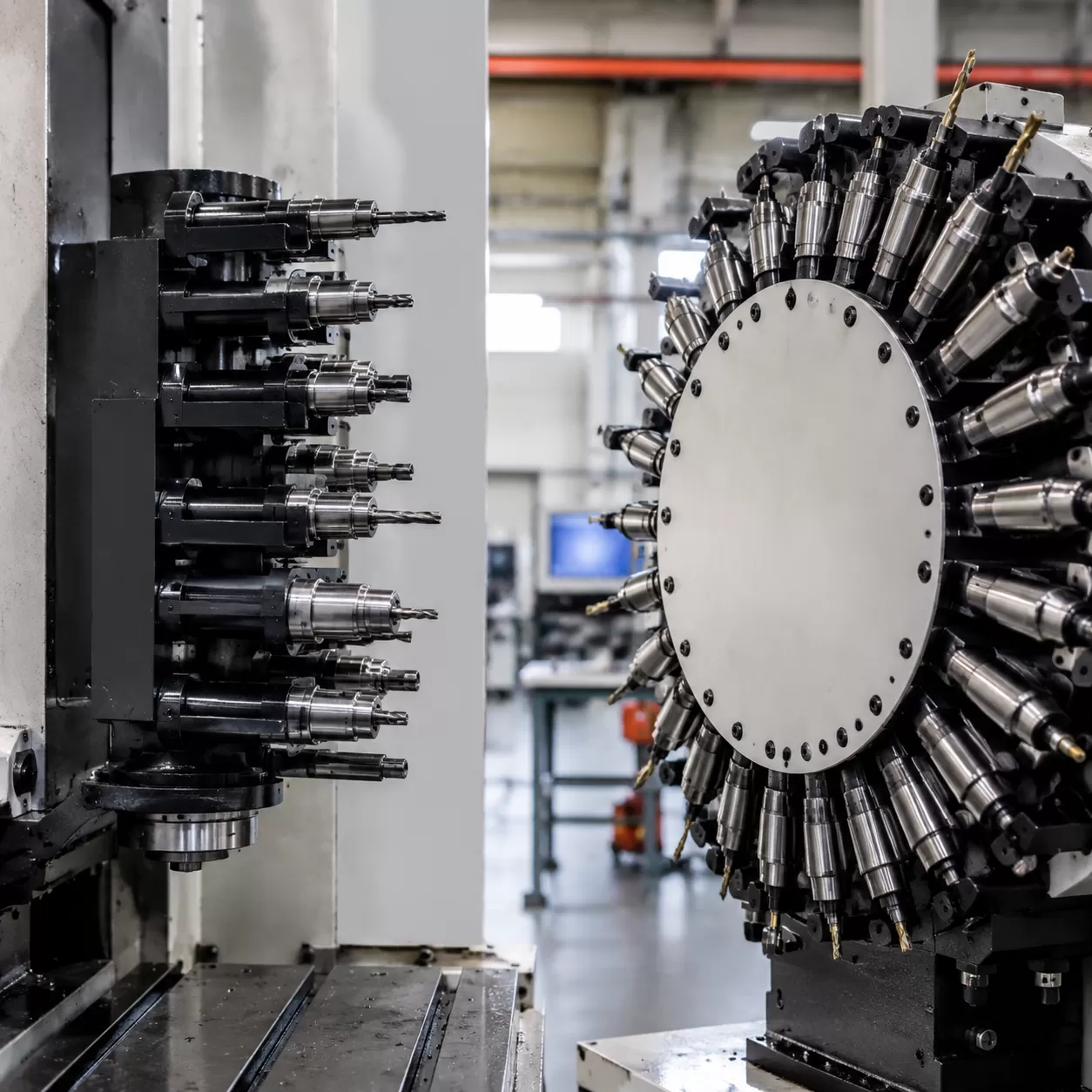
The choice typically comes down to two main configurations: linear rack tools and rotary carousel magazines. Each layout offers distinct mechanical advantages depending on your shop’s volume and footprint.
Fixed Linear Rack Tools: The Bulletproof Budget Option
Fixed linear rack tools are arranged in a straight line, usually along the rear or side edge of the CNC wood router bed. Because the rack is completely stationary, this setup is structurally bulletproof with zero moving parts to wear out. It is a highly reliable, cost-effective solution for shops that want automated tool switching without the premium price tag. For small to medium shops utilizing standard CNC wood routers, a linear rack delivers incredible durability and keeps maintenance to an absolute minimum.
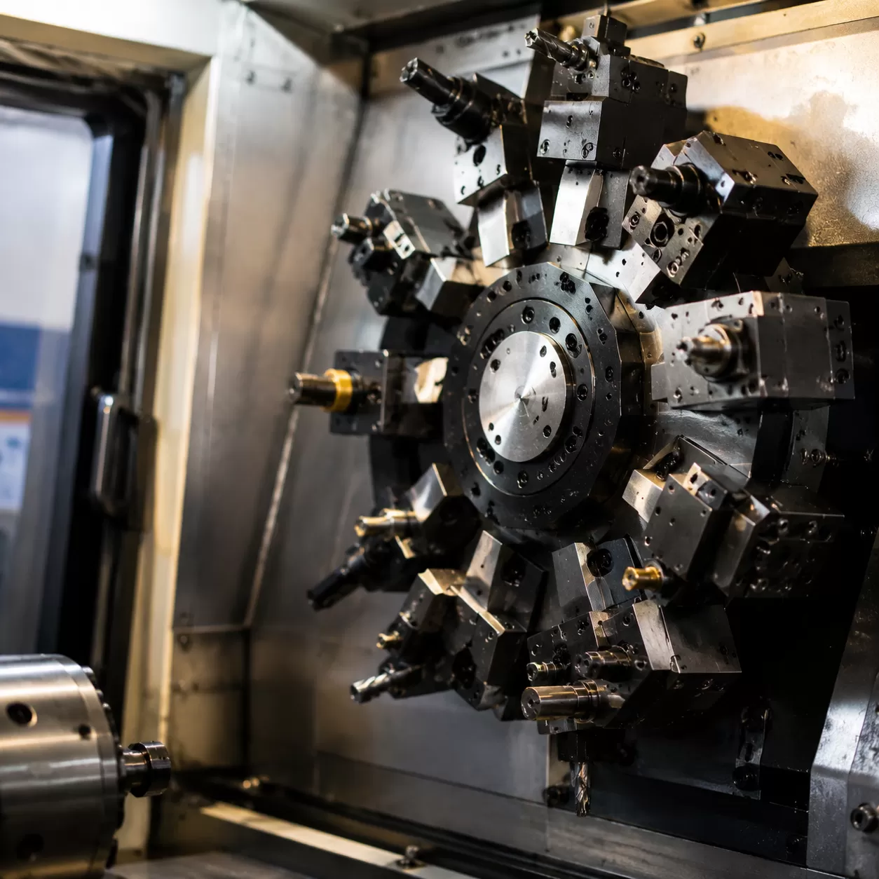
Rotary Carousel Magazines: Built for Pure Speed
If you are running high-density nesting operations where every second counts, a rotary carousel magazine is the superior choice. Mounted directly onto the traveling gantry, the carousel moves with the spindle. This drastically shortens the tool change cycle path because the spindle does not need to travel all the way to the back of the machine bed to swap a tool holder.
Choosing the Right Layout for Your Workshop
| Feature | Linear Rack Tools | Rotary Carousel Magazine |
|---|---|---|
| Mounting Location | Rear or side of the machine bed | Directly on the traveling gantry |
| Travel Distance | Long (Spindle must return to base) | Short (Travels with the gantry) |
| Mechanical Complexity | Extremely low (No moving parts) | Higher (Rotary motor drive system) |
| Best Used For | General woodworking, cabinet doors | High-speed nesting, high-volume production |
Deciding on the right storage layout comes down to balancing your upfront budget against your required production speed. If maximum throughput and shaved seconds are your main goals, the gantry-mounted carousel pays for itself quickly. If simplicity, reliability, and cost-efficiency top your priority list, a linear rack gets the job done flawlessly.
How a CNC ATC Chuck Sensor Keeps Workpieces Flawless
On our automated machines, we eliminate manual calibration entirely. A heavy-duty tool length sensor and Z-axis touch-off plate measure tool length offsets instantly on the fly, updating the controller coordinates before the spindle ever touches the material.
Beyond keeping your cuts precise, the internal automation relies on a strict trio of preventative safety faults monitored by proximity sensors. If these safety indicators fail to register correctly, the CNC machine will halt immediately to prevent catastrophic workpiece or spindle damage:
- Tool Clamped: Confirms the drawbar has successfully locked onto the retention knob and the tool is safe to spin up to high RPM.
- Tool Unclamped: Verifies the pneumatic piston has pushed down completely, fully releasing the holder into the magazine rack.
- Clamped Without Tool: Senses if the drawbar snapped shut on an empty pocket, preventing the spindle from running without a tool holder.
Wood dust is the ultimate enemy of high-speed tooling automation. To protect the inner mechanics, a continuous positive pressure air purge blows through the assembly. This constant airflow creates a physical barrier that keeps micro-dust and resin out of the high-speed precision bearings, ensuring your CNC ATC chuck operates flawlessly through long production shifts.
Keeping Your ATC Chuck Operating Flawlessly
An automatic tool changer is the heart of high-speed tooling automation, but it only delivers peak performance if you maintain it properly. Neglecting basic upkeep directly impacts precision and cuts down the lifespan of your machine. To keep your system running without unexpected downtime, incorporate these three critical maintenance practices into your shop routine:
- Supply Clean, Dry Air: Your pneumatic release sensor and internal pistons rely on a continuous stream of clean air. Always route your shop air through a high-quality coalescing filter to remove moisture and contaminants. Wet air causes internal corrosion, sticking pistons, and sluggish tool releases.
- Wipe Down Tapers Daily: Micro-dust and resin buildup on the tool holder taper or inside the internal spindle taper will cause axial runout. Clean these surfaces daily using a dedicated spindle wiping taper and a lint-free cloth. This simple step ensures flawless mating and preserves cutting accuracy.
- Inspect Retention Knobs Regularly: Under high-RPM duty cycles, the pull studs endure massive lateral loads and repetitive retention knob clamping force. Inspect them weekly for signs of stress, fatigue, or visible wear. Replacing a worn pull stud prevents catastrophic tool release failures during a cut.
If you want to upgrade your production capabilities with robust, reliable hardware, our high-performance ATC CNC router systems are engineered with heavy-duty spindles and premium pneumatic components built to withstand demanding workshop schedules.
| Maintenance Task | Frequency | Target Component | Objective |
|---|---|---|---|
| Filter Check | Daily | Coalescing Filter / Pneumatics | Prevent internal piston corrosion |
| Taper Cleaning | Every Shift | Tool Holder & Spindle | Eliminate axial runout and debris |
| Pull Stud Inspection | Weekly | Retention Knobs | Prevent fatigue failure at high RPM |
By committing to this blueprint, you protect your spindle drawbar mechanism, keep your non-productive cycle time low, and ensure your machine delivers clean, repeatable cuts every single day.
FAQs About CNC ATC Chuck Operations
How much air pressure does a pneumatic release sensor and drawbar mechanism typically require to function?
Most automatic tool changer spindles require a consistent clean air supply between 0.6 to 0.7 MPa (87 to 101 PSI). This pressure is vital for the pneumatic release sensor and internal piston to completely overcome the heavy-duty disc springs. If your pressure drops below the minimum threshold, the drawbar cannot push down far enough to release the tool holder taper safely, stalling your production line.
Can I mix different tool holder taper profiles like BT30 and HSK on the same rotary carousel magazine?
No, you cannot mix different tool holder taper profiles on the same magazine. A rotary carousel magazine or linear rack is specifically machined to accept only one type of tooling geometry, such as ISO20, BT30, or HSK. Furthermore, the internal spindle drawbar mechanism, pull stud engagement, and retention knob clamping force are completely different for each standard. Mixing profiles will cause catastrophic mechanical crashes and ruin the spindle taper.
What happens to the CNC controller command if the spindle purge air fails during a tool change cycle?
If the spindle purge air fails or pressure drops during an M06 CNC controller command, the machine safety interlocks will trigger an immediate emergency stop (E-stop). The controller monitors these pneumatic sensors constantly. If the air blast fails to clear out wood dust, the system halts to prevent chips from getting trapped inside the spindle taper, which would otherwise cause massive axial runout and ruin your machining accuracy. For high-volume production, ensuring your pneumatics are flawless is just as important as choosing the right CNC machining center for your workshop layout.