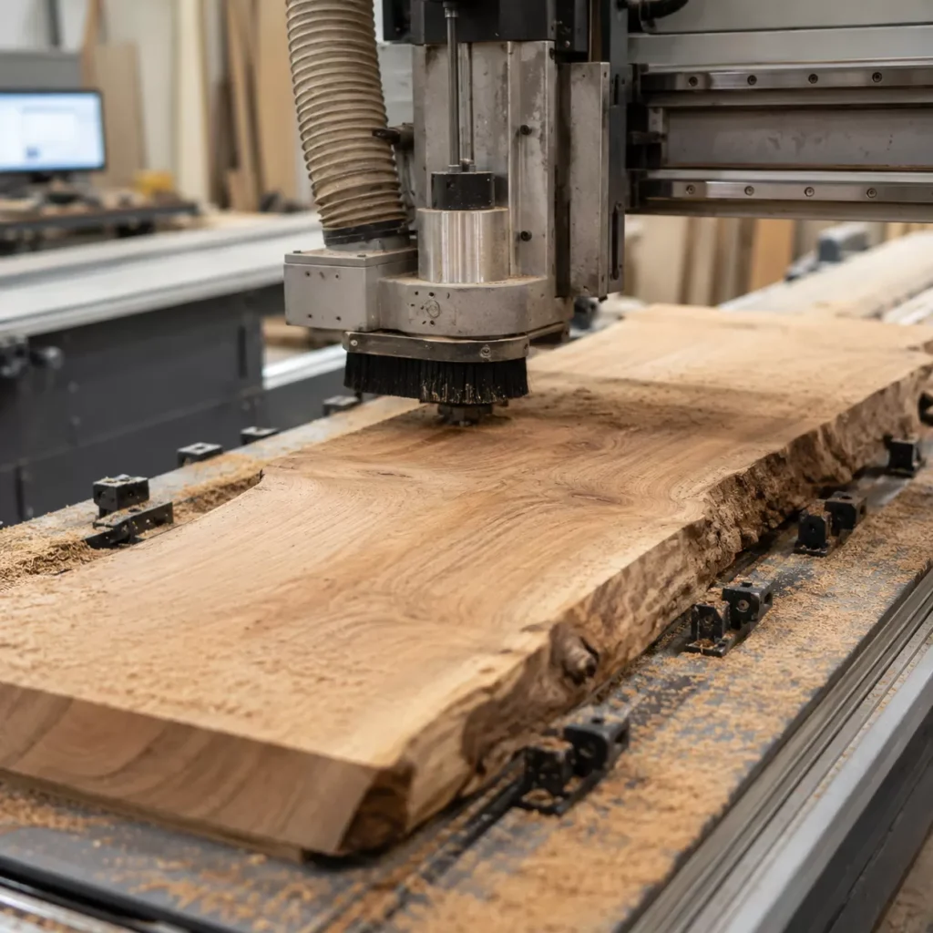
While wide live-edge slabs and highly figured timber look incredible, they are notorious for destroying traditional thickness planers with severe grain tear-out.
That is where your CNC router comes in.
When programmed correctly, your machine acts as the ultimate high-precision thicknessing system. But achieving a perfectly flat, coplanar reference surface requires more than just slapping a board onto the bed and pressing start. You need to understand the precise interaction between machine alignment, specialized tooling, and smart workholding.
In this comprehensive machining guide, we at ProMach break down the exact technical workflow for how to flatten wood on a cnc router. You will learn how to eliminate the “rocking” problem with strategic shimming, select the ideal fly cutter router bit, optimize your CAM software parameters, and eradicate tool ridges.
Let’s dive right into the technical blueprint.
Pre-Machining Checklist
Before you mount a warped live edge slab or a rough piece of lumber to your machine, you need to ensure your machine’s foundation is dead accurate. CNC spoilboard surfacing is the literal starting point of every successful flatting project. If your spoilboard isn’t perfectly parallel to your machine’s X and Y axes, you will never get a perfectly flat piece of stock, no matter how advanced your toolpaths are.
The Foundation of Flatness
A flat cut requires a perfectly flat reference surface. Over time, humidity, heavy use, and mechanical stress cause your CNC spoilboard to warp or compress. I always start by checking the tight integration of the sacrificial board to the machine bed. If the spoilboard moves even a fraction of a millimeter under the cutting pressure of a large slab flattening CNC operation, the final thickness of your wood will be uneven.
The Hidden Culprit of Ridges
Have you ever finished a flattening pass only to find tiny, step-like ridges running along the toolpath lines? This isn’t a issue with your wood; it’s a structural alignment problem known as an untrammed spindle.
When your spindle is slightly tilted relative to the machine bed, a wide fly cutter router bit or spoilboard cutter will cut deeper on one side than the other. Instead of a perfectly smooth, flat surface, you get a series of micro-steps. Even a fraction of a degree off-angle will ruin a premium hardwood slab.
How to Check and Fix Tramming
Perfect spindle tramming means your spindle is exactly 90 degrees perpendicular to the wasteboard in both the X and Y directions.
- The Mechanical Test: Insert a bent rod or a dedicated dial indicator tramming tool into the spindle collet. Rotate the spindle manually by hand to sweep a wide circle across the bed.
- Identify the High Spots: Measure the variance between the front, back, left, and right points of the sweep.
- Adjusting the Z-Axis: Loosen the spindle mount and use precision shim stock or built-in adjustment screws to correct the lean.
- Verification Pass: Once the dial indicator reads zero across the entire sweep, lock down the spindle and run a light skimming pass with your CNC router surfacing bit to create a perfectly flat reference plane.
Selecting the Ultimate Tooling
Choosing the right cutter is the difference between a glass-smooth finish and a ruined hardwood slab. When you learn how to flatten wood on a cnc router, your choice of a cnc router surfacing bit dictates your feed rates, stepover limitations, and the amount of post-machining sanding required.
Anatomy of a CNC Surfacing Bit
A dedicated spoilboard cutter or fly cutter router bit features a unique geometry designed specifically for bottom clearing. Unlike standard end mills, these bits feature multiple carbide inserts positioned at a negative rake angle to shear wood fibers horizontally rather than pulling them vertically. This geometry prevents tear-out on tricky grain, making them essential for slab flattening cnc operations on high-value live edge material.
Matching Shank and Diameter to Spindle Horsepower
You must balance the cut diameter of your bottom clearing router bit with the rigid capability of your machine structure and spindle motor power. For heavy-duty industrial spindles, utilizing heavy-duty CNC spare parts like balanced collets ensures that large-diameter tooling operates without inducing destructive harmonics.
| Spindle Power | Recommended Shank Diameter | Maximum Tool Diameter | Ideal Application |
|---|---|---|---|
| Low Power (1.5 kW – 2.2 kW) | 1/2 inch (12.7mm) | 1.5 inches – 2.0 inches | Small boards, CNC spoilboard surfacing |
| Medium Power (3.0 kW – 4.5 kW) | 1/2 inch or 12mm | 2.0 inches – 2.5 inches | Mid-sized tables, live edge slab flattening |
| High Power (6.0 kW+ / Industrial) | 3/4 inch or 20mm+ | 3.0 inches – 4.0 inches | Large timber, high-volume production |
ProMach Pro-Tip: Never oversize your tool diameter to save time if your spindle lacks the torque. An oversized bit causes the spindle RPM to drop under load, leading to burn marks, severe ridge lines, and premature carbide failure. For optimal results, stick to a tool diameter that allows you to maintain consistent feeds and speeds for flattening wood.
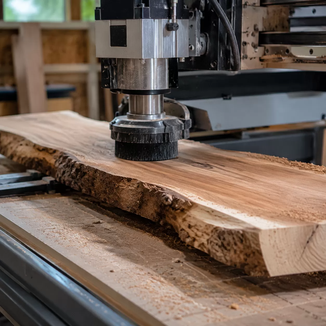
Workholding & Stabilization Strategies for Warped Wood
Flattening live edge slabs or twisted stock requires a strategic approach to workholding. If you secure a warped board incorrectly, you will ruin the cut before the spindle even spins.
The Trap of Mechanical Over-Clamping
Forcing a twisted or cupped board flat against your CNC spoilboard using high-pressure clamps is a critical mistake. When you apply excessive downward force, the wood temporarily flexes flat. The moment the toolpath finishes and you release the clamps, the wood springs right back into its original warped shape. You are left with a piece that has a uniform thickness but remains completely warped.
The “Stop-The-Rock” Analysis
Before securing the stock, place it on the bed and find the high and low spots. Push down on the corners to see where it rocks. The goal of slab flattening CNC work is to eliminate this movement completely without altering the natural rest position of the lumber.
The Shimming Process
To stabilize a problematic board, insert plastic or wooden shims underneath the gaps and low spots identified during your analysis.
- Find the voids between the timber and the bed.
- Slide shims into place until the rocking stops.
- Secure the shims with hot glue or blue painter’s tape so they cannot migrate during machining.
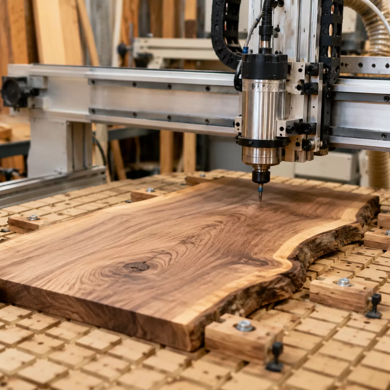
Carrier Board Workflows
For severely warped, small, or irregular pieces, standard clamping fails. In our shop, we rely on a sacrificial carrier board workflow.
- Mount the warped stock onto a flat piece of MDF or plywood using hot glue and shims.
- Secure this secondary carrier board to your 3-axis CNC wood router using standard table clamps or a vacuum grid.
- Machine Face A completely flat.
- Flip the workpiece, remove the carrier board, and reference the newly flattened face directly against your main spoilboard to finish the project.
CAM Software Programming & Toolpath Strategy for Flattening Wood on a CNC Router
When learning how to program a CNC machine for slab flattening, your software strategy is just as critical as your physical setup. Proper toolpath selection prevents tear-out, saves time, and protects your surfacing bit.
Choosing Your CNC Facing Toolpath
For flattening wood slabs, a raster (zig-zag) toolpath or a pocket toolpath CNC strategy are the two best options.
- Raster Toolpath: Best for grain-aligned clearing. Program the machine to cut parallel to the wood grain to minimize tear-out and yield the smoothest finish.
- Pocket Toolpath (Offset): Moves from the inside out or outside in. While efficient, it forces the cutter to transition across end grain frequently, which can cause minor chipping on the edges of live edge slab flattening projects.
The Safe Entry/Exit Rule
Never plunge a wide-diameter spoilboard cutter directly down into raw stock. Always program a ramp entry or lead-in path outside the material boundaries. Entering the wood horizontally or at a shallow angle prevents spindle deflection, eliminates burn marks, and extends tool life.
Optimizing the Stepover Percentage CNC
The stepover percentage dictates how much the tool overlaps on each pass. For a clean, ridge-free surface, balance speed with finish quality:
- Recommended Stepover: 30% to 40% of the total cutter diameter.
- Why it matters: Excessive stepover leaves uncut ridges (witness lines), while too little stepover wastes time and causes friction-induced burning. For a $2.5\text{-inch}$ fly cutter router bit, a stepover of $0.75$ to $1\text{-inch}$ is ideal.
Determining Depth of Cut (DOC)
Warped wood requires a conservative depth of cut to handle unpredictable high spots.
- Maximum DOC: Keep the depth between $0.03\text{-inches}$ ($0.8\text{ mm}$) and $0.06\text{-inches}$ ($1.5\text{ mm}$) per pass.
- The Strategy: It is always safer and more efficient to run two rapid, shallow passes rather than forcing the spindle to plow through a heavy, uneven load in a single pass.
Calculating Feeds, Speeds, and Cutting Direction for Slab Flattening
Dialing in the correct feeds and speeds is the difference between clean wood chips and a burnt, ruined slab. When you flatten wood on a CNC router, you need to maintain the proper chip load to keep the cutter cool and prolong tool life.
The Formula for Clean Chips
To prevent wood from burning or fuzzy tear-out, calculate your chip load using this standard CNC formula:
$$\text{Feed Rate} = \text{RPM} \times \text{Number of Flutes} \times \text{Chip Load}$$
For a typical large-diameter fly cutter router bit, you want to target a heavy chip load ($0.003\text{ to }0.005\text{ inches per tooth}$) to ensure the bit is actually cutting wood rather than rubbing against it and generating heat.
Baseline Parameters Reference Table
These baseline settings work efficiently for standard 2.2kW to 4kW spindles running a $2\text{-inch}$ to $2.5\text{-inch}$ CNC router surfacing bit:
| Wood Type | Spindle Speed (RPM) | Feed Rate (IPM) | Depth of Cut (DOC) | Stepover % |
|---|---|---|---|---|
| Softwoods (Pine, Cedar) | 12,000 – 14,000 | 200 – 250 | Up to $0.125\text{ inches}$ | 40% – 50% |
| Hardwoods (Oak, Walnut) | 10,000 – 12,000 | 150 – 180 | $0.040\text{ to }0.060\text{ inches}$ | 30% – 40% |
| Exotics / Highly Figured | 10,000 | 120 – 140 | Max $0.030\text{ inches}$ | 25% – 30% |
Climb Cutting vs. Conventional Milling
Choosing the right cutting direction prevents edge tear-out and improves the overall surface finish on large live edge slab flattening jobs.
- Climb Cutting: The tool rotates with the direction of the feed. This creates a thick-to-thin chip profile, reducing fuzziness and leaving an incredibly smooth top surface. It is the preferred method for the final pass.
- Conventional Milling: The tool rotates against the feed direction. It forces the chip from thin to thick, which can cause lifting and tear-out along grainy edges but puts less stress on rigid CNC milling machines during heavy material removal.
For the best results on unpredictable wood grain, run your roughing passes using conventional milling to hog off the warped stock, then switch to a light climb cutting pass for the final $0.010\text{ inches}$ to achieve a flawless finish.
Execution
With your CNC setup dialed in, it is time to execute the slab flattening CNC process. Following a strict sequence ensures safety, protects your tooling, and guarantees a perfectly parallel result on both faces of your stock.
Step 1: Metal Detection Sweep
Before spinning up your metal CNC router or woodworking spindle, pass a handheld metal detector over the entire surface of the wood. Hidden nails, fencing staples, or broken screws will instantly ruin an expensive carbide surfacing bit and can pose a serious safety hazard.
Step 2: Z-Axis Probing
Set your machine’s X and Y zeroes at your starting corner. For the Z-axis, locate the lowest point on the warped wood slab to set your initial reference if you want to ensure total cleanup, or probe the highest spot if you need to take light, incremental passes to avoid overloading the spindle.
Step 3: Executing Face A
Mount the wood securely using your shimming strategy and start the CNC facing toolpath. Keep your hand near the E-stop during the first pass to monitor how the cutter engages the material. Let the machine clear the entire top surface until Face A is completely flat and smooth.
Step 4: Flipping and Parallel Face B Machining
Vacuum away all wood chips, release the workholding, and flip the slab over onto your flat CNC spoilboard. Since Face A is now perfectly flat against the table, you no longer need shims. Clamp the stock down directly and run the toolpath on Face B. This second operation creates a uniform thickness across the entire board, leaving you with two perfectly parallel faces.
Post-CNC Surface Conditioning
Even with a perfectly calibrated machine, flattening wood on a CNC router will often leave faint visual tracks or minor textures on the wood surface. These witness lines are completely normal and mark the transition between the toolpath passes. Achieving a flawless, showroom-quality finish requires a deliberate post-machining sanding progression to erase these artifacts without altering the flatness you just achieved.
Erasing Witness Lines
Witness lines are usually just a fraction of a millimeter deep. If your spindle tramming was accurate, these lines will feel completely smooth to the touch but remain visible to the eye.
- Avoid heavy hand pressure: Pushing down too hard on a random orbital sander can create low spots, ruining the precision of your slab flattening CNC work.
- Use a hard backing pad: A firm sanding pad keeps the abrasive flat across the ridges rather than dipping into the valleys.
- Check with low-angle lighting: Direct a flashlight or shop light flat across the wood surface to cast shadows on any remaining tool marks.
Sanding Progressions
The secret to efficient surface conditioning is never skipping a grit sequence. For hardwoods flattened with a high-quality surfacing bit, start your progression at a grit coarse enough to cut the lines but fine enough to preserve the flat plane.
| Sanding Phase | Grit Level | Purpose |
|---|---|---|
| Initial Clean-up | 80 – 100 Grit | Rapidly removes CNC tool marks, fuzz, and witness lines. |
| Surface Smoothing | 120 – 150 Grit | Erases scratches from the initial pass and preps wood for uniform absorption. |
| Finish Prep | 180 – 220 Grit | Closes the grain perfectly for oils, film finishes, or epoxy pours. |
Always vacuum the wood dust between grits. Leftover coarser particles can get trapped under the sander during the next phase, creating deep swirl marks that require you to start the entire process over again.
Tool Maintenance and Shop Safety for Flattening Wood on a CNC Router
Keeping your machine and tooling in peak condition is the final, non-negotiable step when you learn how to flatten wood on a cnc router. Neglecting maintenance ruins expensive bits, spoils your workpieces, and creates serious shop hazards.
Resin and Pitch Removal
Wood species like pine, cherry, and walnut leave behind resin and pitch buildup on your surfacing cutters. This baked-on residue increases friction, traps heat, and dulls your carbide inserts prematurely.
- The Fix: Spray the bit with a dedicated pitch remover or citrus-based cleaner.
- The Action: Let it sit for a few minutes, then scrub the residue away with a brass wire brush. Never use steel wire brushes, as they can chip the sharp carbide edges.
Torque and Indexing
Most high-end flattening bits use indexable carbide inserts. When one edge dulls, you rotate it to a fresh side. However, improper installation will cause uneven cuts and ridges on your timber.
- Clean the Pockets: Before seating a new or rotated insert, use compressed air to blast out any dust from the pocket. A single speck of dust can cock the insert slightly out of alignment.
- Proper Torque: Use a torque wrench to tighten the insert screws to the manufacturer’s exact specifications. Over-tightening cracks the carbide, while under-tightening allows the insert to shift mid-cut.
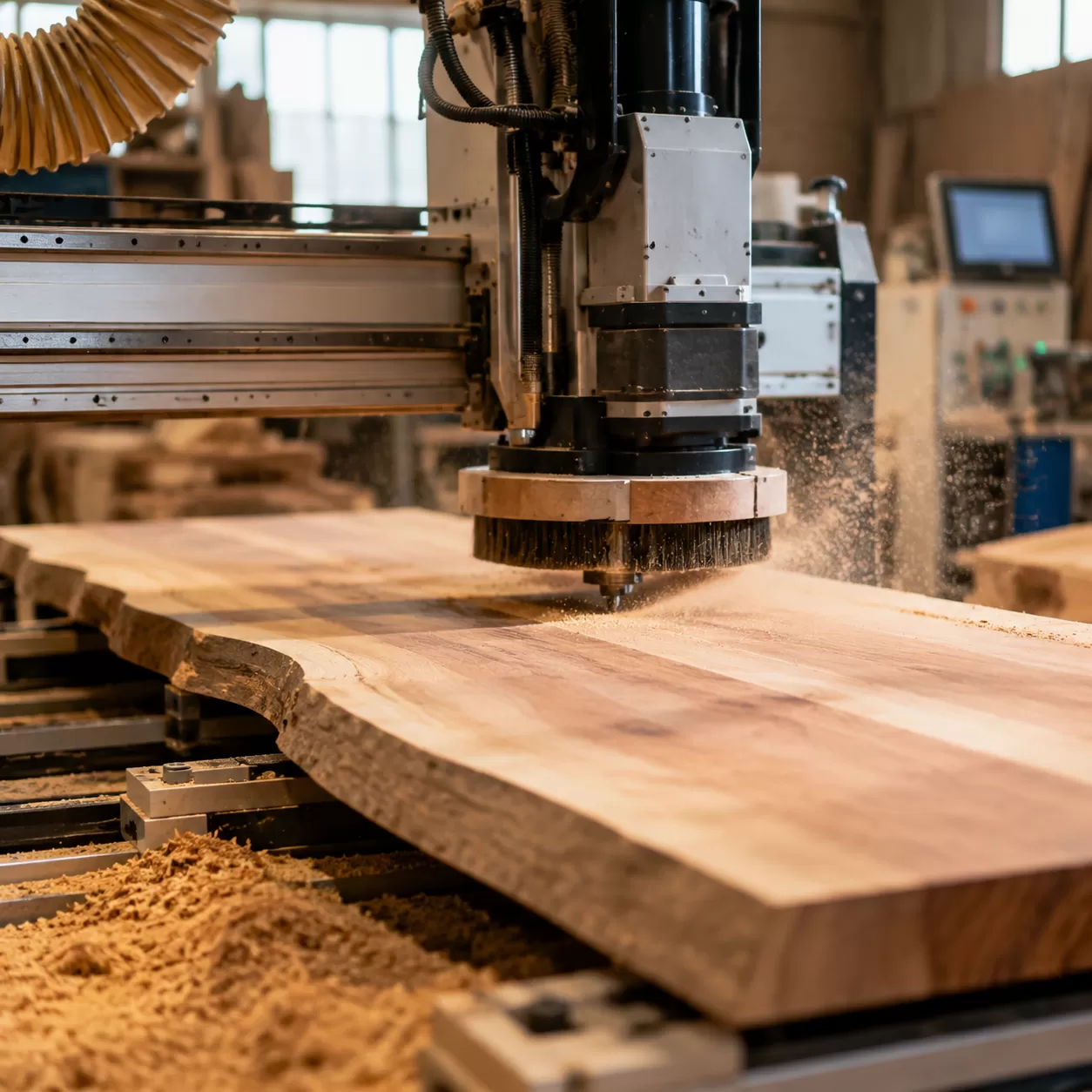
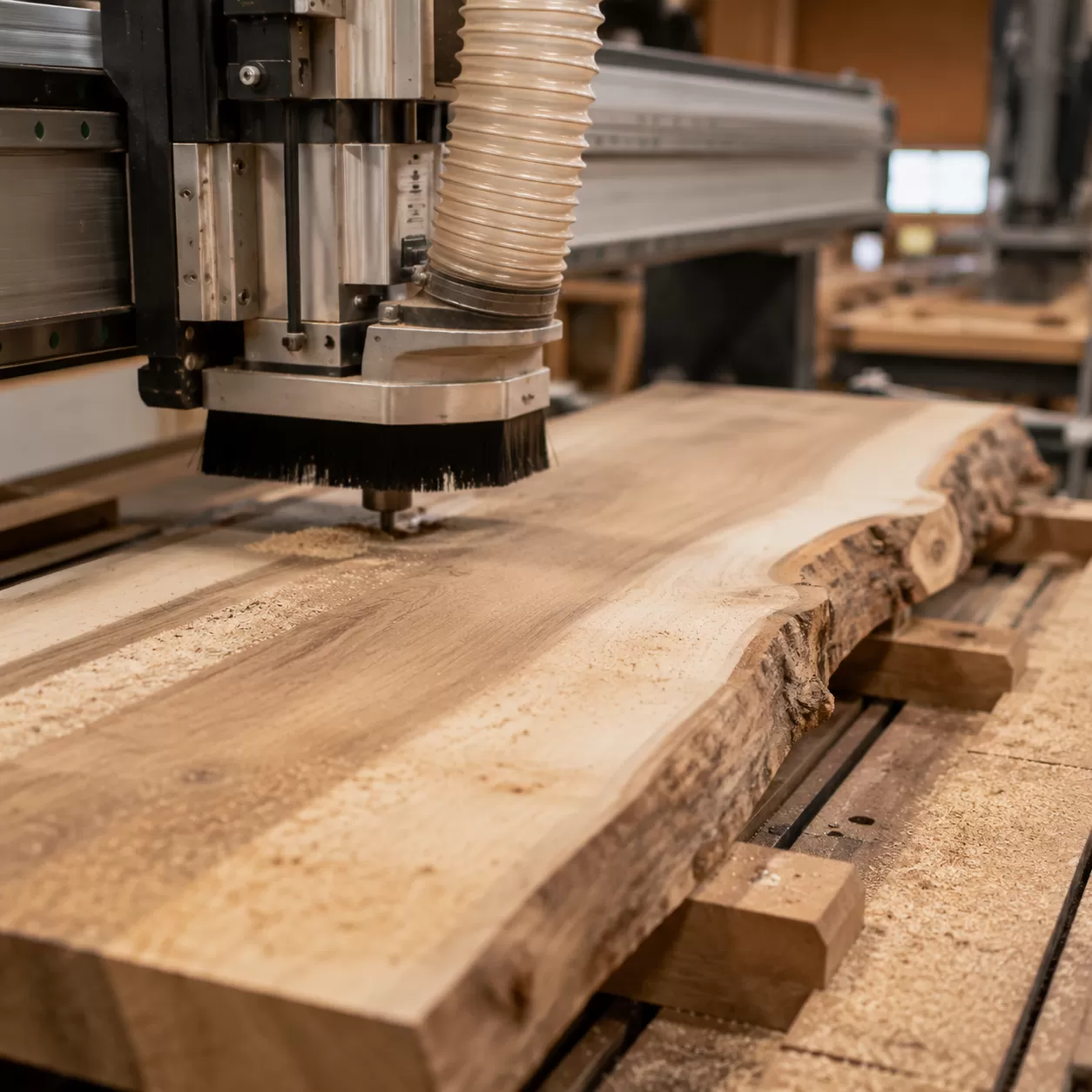
Dust Control
Flattening large wood slabs or surfacing a heavy-duty cnc wood router spoilboard generates a massive volume of fine dust and heavy chips. Without proper extraction, this debris packs into the cut path, causing the bit to re-cut chips, overheat, and potentially ignite.
Safety Warning: Always run a high-volume dust collection system with a properly fitted dust boot. For massive slab-flattening operations, wearing a well-fitted particle mask is essential to protect your lungs from fine airborne particulate.