
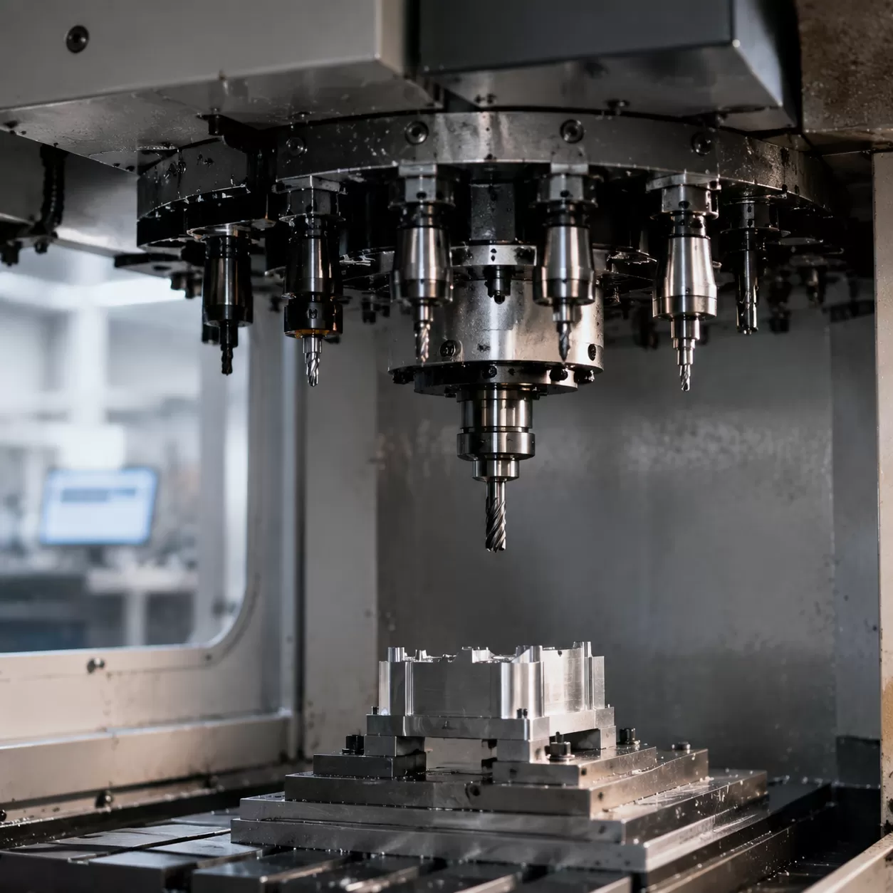
Anatomy of an ATC Spindle
In high-efficiency CNC wood routers production, the Automatic Tool Changer mechanism (ATC) is what makes non-stop manufacturing possible. But to trust an automated system with your high-speed router bits, you need to understand exactly what happens inside the heart of the CNC spindle.
The ATC spindle is not just a motor; it is a precision mechanical clamping device. It relies on a perfectly synchronized stack of internal components to hold tool holders with absolute rigidity at speeds up to 24,000 RPM. Let’s tear down the spindle and look at the core components that make up this reliable clamping system.
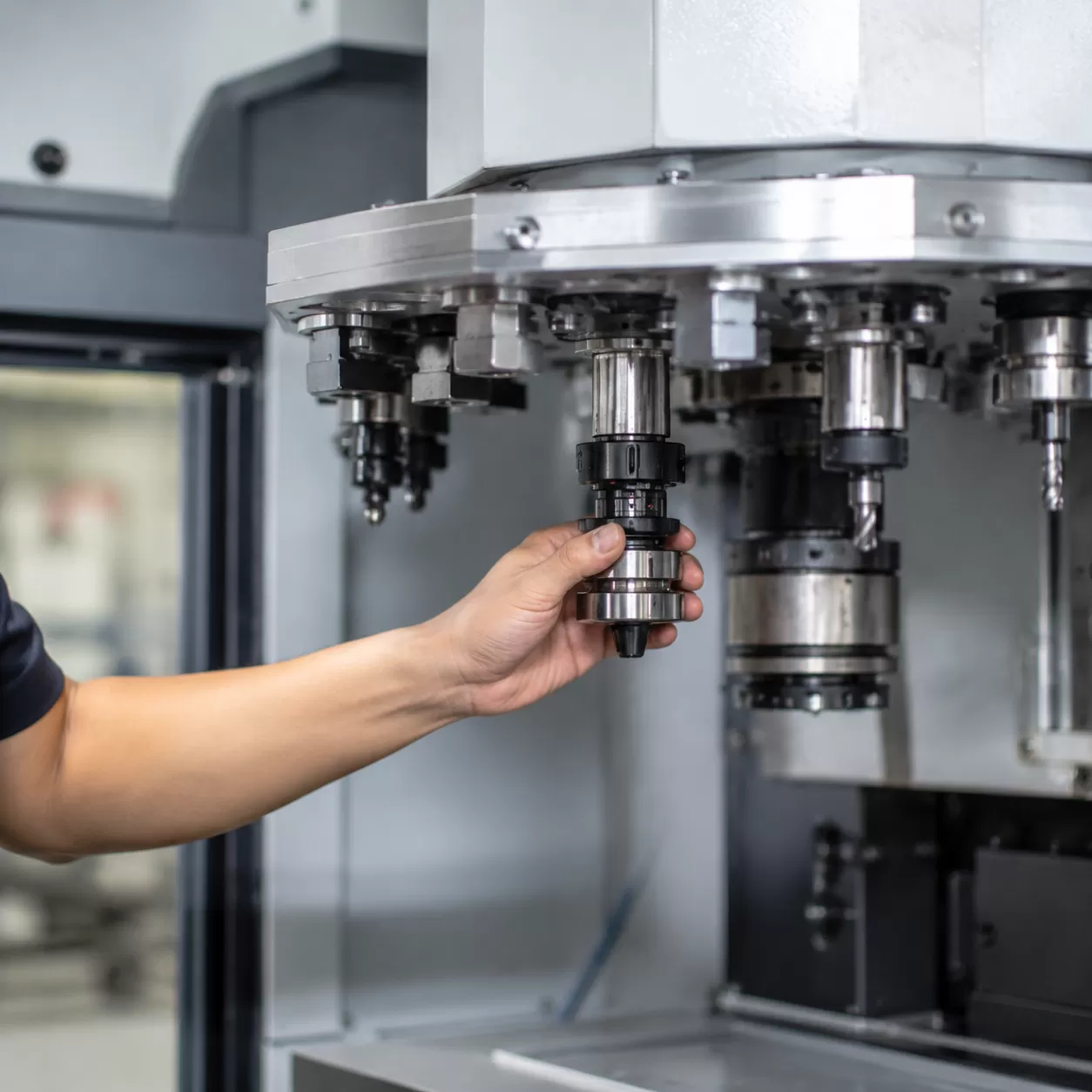
The Tool Holder & Cutting Tool Shank
In ATC systems, we do not clamp the router bits directly into the spindle shaft. Instead, the cutting tool is secured into a precision tool holder (typically ISO30, HSK63F, or BT30) using an ER or SY collet.
| Component Feature | Industrial Standard / Impact |
|---|---|
| Taper Interface | Precision ground to match the internal spindle taper perfectly. |
| Concentricity | Ensures router bits concentricity to eliminate chatter marks on wood panels. |
| Shank Grip | Rigidly locks the cutting tool shank to prevent tool pull-out under heavy feed rates. |
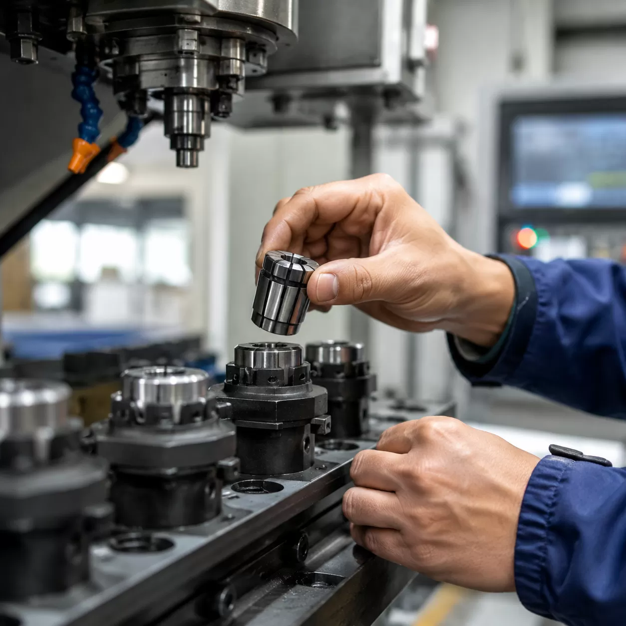
The Pull Stud / Retention Knob
Sitting at the very top of the tool holder is the retention knob, often called the pull stud. This small, hardened steel component is the literal handle that the internal spindle mechanism grabs onto.
- Engineered Geometry: The specific angle of the retention knob head must match the spindle’s internal gripper fingers exactly.
- Massive Retention Force: It withstands thousands of pounds of pull-force to keep the tool seated under heavy axial and radial routing loads.
- Wear Point: Because it experiences constant mechanical engagement, tracking retention knob clamping force and checking for wear is a vital safety habit.
Heavy-Duty Disc Springs (Belleville Washers)
How does a spindle maintain tight mechanical clamping force without relying on continuous air pressure or electricity? The secret lies in a tightly compressed stack of heavy-duty disc springs, commonly known as Belleville washers.
- Mechanical Default State: These springs provide the mechanical force that pulls the internal drawbar upward, locking the tool into the spindle taper by default.
- Failsafe Design: If your workshop experiences a sudden electrical failure or pneumatic system pressure drop, the mechanical force of these disc springs keeps the tool locked safely inside the spindle.
- Constant High Pressure: They exert a continuous, massive clamping force that prevents any axial runout prevention or micro-movements during heavy nested-based nesting cuts.
The Internal Drawbar & Gripper Fingers (Collet Claws)
Running straight through the center of the CNC spindle shaft is the CNC spindle drawbar. At the bottom end of this mechanism sits the actual clamping element: the collet (sometimes informally referred to as collet claws in non-technical descriptions).
[Drawbar Shaft]
│
▼ (Spring force pulls UP to apply clamping force)
[Collet / Clamping Fingers] ──► Segmented design contracts radially when pulled into the taper
│
▼ (Clamps onto)
[Retention Knob / Pull Stud]
When the disc springs pull the drawbar upward, the collet is drawn upward into the spindle taper. This causes the segmented collet to contract inward, securely gripping the retention knob. The system then generates a high axial clamping force, pulling the entire tool holder upward until it seats firmly and precisely in the spindle taper.
The Pneumatic Unclamp Unit
To swap tools, the machine must overcome the massive mechanical force of the Belleville disc springs. This is where the pneumatic unclamp unit comes into play, sitting at the very top of the spindle assembly.
- Air Pressure Actuation: When an M06 tool change command is triggered, a heavy pneumatic cylinder fires downward.
- Overcoming Spring Force: The cylinder piston physically hits the top of the internal drawbar, pushing it down against the disc spring stack.
- Tool Release: Pushing the drawbar down relaxes the gripper fingers (collet claws), releasing their hold on the retention knob and allowing the tool holder to drop smoothly out of the spindle taper.
The Step-by-Step Choreography of an ATC Tool Change Cycle
Understanding how does cnc atc collet work requires looking at the seamless automation of the Automatic Tool Changer mechanism. During high-speed machining operations, a tool change is a highly coordinated mechanical dance executed in seconds to keep production efficiency peaked.
Phase 1: The G-Code Trigger (M06 Command)
The entire sequence kicks off inside the controller. When the execution software hits an M06 command (e.g., M06 T2), the CNC wood router halts its active cutting path.
- The spindle retracts safely along the Z-axis.
- The system reads the tool geometry data for the incoming selection.
- The machine commands the servo driven mechanism or carousel to position the new tool holder for pickup.
Phase 2: Spindle Braking and Position Orientation
Before any mechanical release can happen, the CNC spindle must come to a flawless, dead stop.
- Dynamic Braking: Resistors rapidly slow the spinning shaft to zero RPM.
- Spindle Orientation: The spindle rotates slowly to a precise, pre-defined angular position. This ensures the drive dogs on the spindle nose align perfectly with the notches on the incoming ATC CNC router tool holder.
Phase 3: Pneumatic Actuation & The Mechanical Unclamping Squeeze
Once positioned, the pneumatic unclamp unit at the top of the spindle fires into action.
- High-pressure air forces a piston downward against the heavy-duty Belleville disc springs.
- This axial movement shoves the internal drawbar down, forcing the gripper fingers (collet claws) to expand outward.
- The mechanical grip on the tool’s retention knob relaxes, completely freeing the current tool so the changer fork can slide it out of the spindle taper.
Phase 4: Tool Taper Seating & Failsafe Clamping Force Mechanical Return
With the old tool stored, the spindle moves over the new tool holder, plunging the spindle taper directly over the fresh cutting tool shank.
[Pneumatic Pressure Releases] ➔ [Belleville Springs Snap Back] ➔ [Drawbar Retracts] ➔ [Gripper Claws Lock Retention Knob]
The pneumatic system then vents its air pressure. Instantly, the massive mechanical energy stored in the Belleville disc springs snaps the drawbar back upward. This high-velocity return forces the gripper fingers to close tightly around the new tool’s retention knob, pulling the taper deep into the socket with thousands of pounds of clamping force. This failsafe mechanical return guarantees the router bit maintains absolute concentricity and zero axial runout, even if the factory completely loses air pressure mid-cut.
Built-In Safety Systems & Real-Time Monitoring
High-speed machining operations require absolute precision, especially when an automatic tool changer mechanism is cycling through tools. To prevent catastrophic failures, our CNC wood routers integrate real-time electronic and pneumatic monitoring safeguards directly into the spindle assembly.
Drawbar Position Monitoring Sensors
The CNC spindle drawbar relies on highly calibrated proximity sensors to verify its exact physical state during a tool change. These sensors constantly monitor the drawbar’s travel distance to detect three distinct conditions:
- Tool Unclamped: Confirms the gripper fingers have fully released the retention knob so the carousel can safely remove the tool holder.
- Tool Clamped: Verifies that a tool holder shank is properly engaged and locked with the correct clamping force.
- No Tool Present: Alerts the system if the spindle executes a clamp command without a tool in the taper, preventing the machine from running empty.
If the sensors detect an incorrect drawbar position, the controller instantly triggers an emergency stop to halt operation before the spindle can spin up.
Vibration Sensors
Advanced monitoring utilizes internal accelerometer sensors to track real-time dynamic balance. High axial runout or a improperly seated router bits shank will cause micro-vibrations at high RPMs. When these vibrations exceed a strict threshold, the safety system slows down or pauses the cutting cycle. This immediate response protects the precision spindle bearings from premature wear and ensures clean, chatter-free cuts on your workpieces.
Pressure Drop Interlocks
The pneumatic unclamp unit requires consistent, high-pressure air to overcome the heavy-duty Belleville disc springs during a tool release. Our machines feature integrated pressure drop interlocks that continuously read incoming pneumatic line pressure. If the air pressure dips below the safe operating limit, the interlock system locks down the tool changer cycle. This prevents the pneumatic actuator from attempting a partial release, ensuring the tool holder never gets stuck or dropped mid-shuttle.
The Ultimate Enemies of Tooling Automation
In high-speed machining operations, precision is everything. When dealing with an automatic tool changer (ATC) system, even a microscopic layer of debris can disrupt the entire production cycle. Contamination and axial runout are the silent killers of spindle longevity and cut quality.
The Danger of Wood Dust & Resin
Woodworking environments are inherently harsh. Fine wood dust and sticky resin are constantly airborne during heavy milling. If these particles find their way into the CNC spindle drawbar or settle on the tool holder taper, they create a physical barrier.
This micro-layer of contamination causes several critical issues:
- Misalignment: The tool holder fails to seat perfectly true inside the spindle taper, leading to increased axial runout.
- Vibration and Marring: Even a few microns of runout will cause router bits to vibrate, ruining the surface finish of your workpiece and accelerating tool wear.
- Clamping Force Reduction: Resin buildup on the gripper fingers (collet claws) or retention knob can prevent the drawbar from achieving its full locking force, creating a massive safety hazard.
For shops running high-volume production on a 1325 CNC wood router, keeping this interface pristine is the difference between flawless edge bands and wasted material.
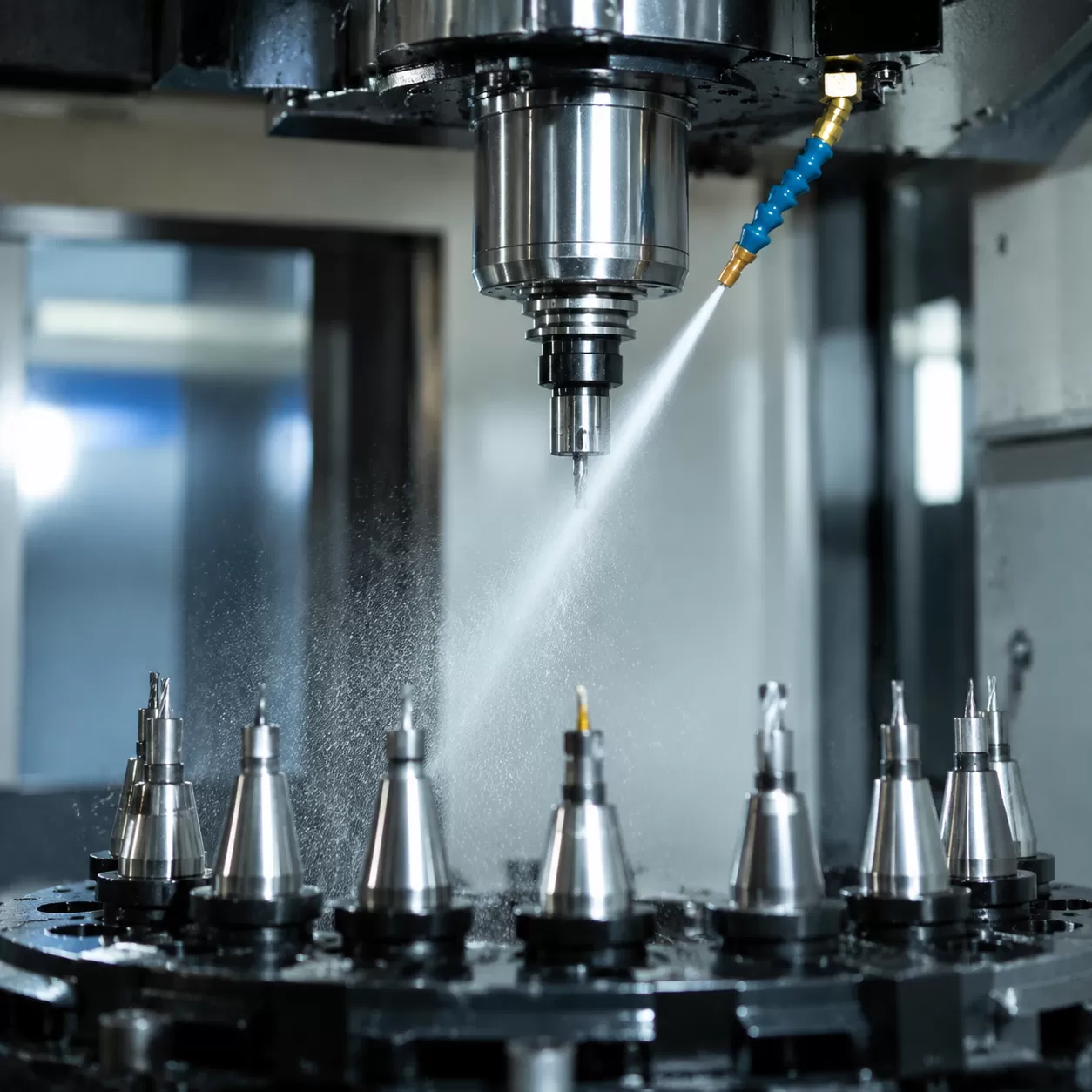
ProMach’s Engineered Defense
To completely eliminate this issue, our machines utilize an active, engineered defense mechanism: Positive Pressure Air Purge.
[Compressed Air Supply] ──> [Internal Spindle Channels] ──> [Airflow Through Spindle / Taper Area]
│
(Helps prevent dust ingress & resin buildup)
Instead of relying solely on passive sealing, the system continuously supplies clean, dry compressed air through internal spindle passages and around the spindle nose area. This creates a positive pressure environment that helps reduce dust and moisture ingress near the tool interface. When the pneumatic unclamp system activates during a tool change cycle, an additional air blast helps clear the spindle taper and tool holder interface. This reduces the risk of dust or resin accumulation on mating surfaces, helping maintain consistent tool seating accuracy and improving overall CNC wood router reliability and production efficiency.
Maintenance Best Practices for Maximum ATC Longevity
Keeping an automatic tool changer mechanism running at peak performance requires a proactive approach. In CNC wood routers production efficiency depends directly on the reliability of the spindle and tool holder interface. Neglecting basic upkeep leads to premature wear, dropped tools, and expensive downtime.
Air Quality Management
The pneumatic unclamp unit relies entirely on clean, bone-dry air to actuate the CNC spindle drawbar. Moisture and debris within the pneumatic system are primary causes of internal corrosion and sluggish mechanical response.
- Daily Moisture Checks: Drain all air compressor filters and water traps before starting machining operations.
- Multistage Filtration: Implement a dedicated air dryer and a sub-micron oil/water separator immediately upstream of the CNC machine.
- Pressure Stability: Ensure the incoming pneumatic line maintains a stable pressure to prevent incomplete tool release cycles.
Daily Taper Cleaning Protocols
Wood dust, resin, and fine particulates easily find their way into the spindle taper during high-speed cutting. Even a microscopic layer of contamination disrupts the tool holder alignment, causing axial runout and reducing router bits concentricity.
- Manual Wipe Down: At the end of every shift, use a lint-free cloth and a light degreasing agent to clean the internal spindle taper and the tool holder cones.
- Taper Cleaning Sticks: Utilize specialized taper cleaning brushes or fleece wipers to safely remove stubborn resin buildup without scratching the precision surfaces.
- Rust Prevention: Apply an ultra-thin layer of high-quality spindle oil to the taper to prevent oxidation, especially in high-humidity workshop environments.
Drawbar Pull-Force Calibration
The Belleville disc springs inside the spindle provide the critical retention knob clamping force required to hold the tool securely at high RPMs. Over millions of cycles, these springs can fatigue, leading to a drop in pull-force that threatens both safety and part accuracy.
| Maintenance Interval | Action Item | Target Metric / Tool |
|---|---|---|
| Every 3 Months | Inspect retention knobs for wear, pitting, or deformation. | Replace any damaged knobs immediately. |
| Semi-Annuallly | Measure the drawbar pull-force using a specialized digital clamping force gauge. | Must meet manufacturer specifications (typically 4,000–10,000+ N depending on taper size). |
| Annually | Verify drawbar monitoring sensors calibration and check for spring stack degradation. | Readjust sensor positioning or rebuild the spring stack if force falls below 90% of spec. |
Regular calibration ensures the gripper fingers (collet claws) maintain an unyielding grip on the tool holder, eliminating axial deflection and protecting the machine spindle from catastrophic failure.
FAQs About CNC ATC Collet Mechanisms
Why is my ATC dropping tools during a tool change?
When an automatic tool changer mechanism drops a tool holder, it is usually a sign of a critical drop in retention knob clamping force. Over time, the internal Belleville disc springs can fatigue or fracture, reducing their ability to pull the drawbar tightly.
Another frequent culprit is insufficient air pressure entering the pneumatic unclamp unit, which prevents the gripper fingers (collet claws) from fully opening or closing at the right moment. This issue is common in busy production environments utilizing advanced high-speed CNC machining centers for heavy nesting.
- Worn Claws: Inspect the internal gripper fingers for physical wear or chips.
- Debris Buildup: Wood dust mixed with grease can mechanically jam the collet claws.
- Sensor Misalignment: Ensure the drawbar monitoring sensors are reading the correct position before the spindle moves.
How often should I test the drawbar clamping force?
We recommend testing the clamping force of your CNC spindle drawbar every 150 to 200 operating hours, or at least once a month. Because safety and axial runout prevention depend entirely on this mechanical connection, relying on guesswork can ruin both your workpiece and your spindle bearings.
| Usage Level | Shift Frequency | Testing Interval | Action Item |
|---|---|---|---|
| Light | Single Shift (Partial) | Every 2 Months | Visual check + force gauge test |
| Medium | Single Full Shift (Daily) | Monthly | Clean taper + force gauge test |
| Heavy | Multi-shift / 24/7 Production | Every 2 Weeks | Deep clean + force gauge calibration |
Regular tracking prevents a sudden loss of router bits concentricity, preserving your overall CNC wood routers production efficiency.
What air pressure do I need for a pneumatic unclamp unit?
Most standard pneumatic unclamp unit systems require a clean, dry air supply running at 0.6 to 0.7 MPa (6 to 7 Bar, or roughly 85 to 100 PSI).
Maintaining this precise pressure window is vital for the machining operations cycle time. If the air pressure is too low, the pneumatic piston will fail to fully compress the heavy-duty Belleville disc springs, preventing a clean tool release. If the pressure is too high, it causes unnecessary impact and accelerated wear on the internal spindle components during the tool change. Always combine this with a positive pressure air purge system to keep the mating surfaces free of contamination.