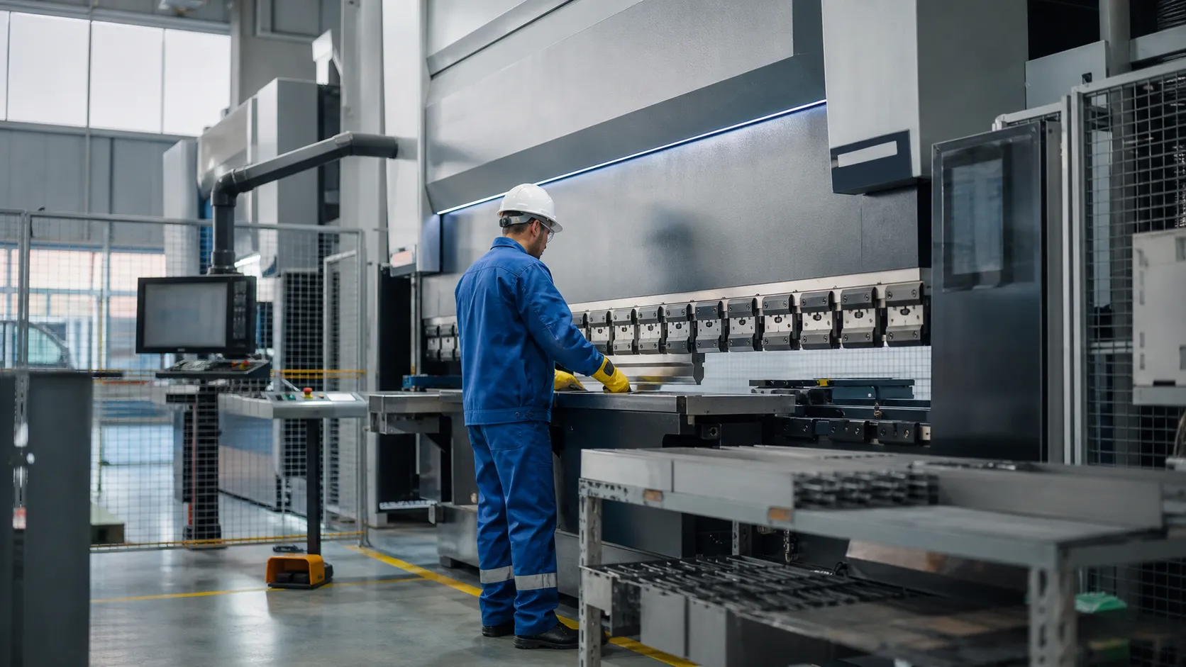
Overview
Cnc bending machine manual pdf files bundle operation manual chapters, electrical schematics, and programming instructions for Delem, ESA, Cybelec, and ProMach SmartCNC controllers.
Who needs these manuals? Maintenance engineers and operators commissioning hydraulic bending machine or servo press-brake lines in sheet metal fabrication plants.
What is included? Press brake user guide setup steps, tooling setup guide checklists, maintenance instructions, alarm tables, and safety operating procedures in searchable PDF format.
Applicable Machine Series & CNC Controller Systems
Manual bundles align with the CNC bending machine product hub and cover electro-hydraulic and full-electric press-brake lines.
This cnc bending machine manual pdf (cnc bending machine pdf) resource covers our full range of high-precision metal forming equipment, from standard workshop units to custom high-tonnage industrial press brakes.
- Supported Machine Models: Electro-Hydraulic Servo and Full Electric Servo Press Brakes (40T to 1000T+ capacity).
- Controller System Compatibility:
- Delem: DA-50T, DA-60T, and DA-69T multi-axis controllers.
- ESA: S600 series touchscreen controls.
- Cybelec: CybTouch and ModEva interfaces.
- ProMach SmartCNC: Native touch interface for multi-axis position control.
Official Documentation Metadata & Compliance Standards
Every press brake user guide and technical manual in our system adheres to strict international manufacturing standards.
| Technical Parameter | Specification Standard |
|---|---|
| Documentation Standard | ISO9001 Certified Documentation System |
| Safety Compliance | CE export compliance certification |
| Revision ID | Rev. 2026-v4.2 |
| Document Delivery | Searchable, print-ready PDF format |
Direct Technical PDF Download Portal
Download verified technical files directly for installation, daily operation, and emergency troubleshooting:
- Full CNC Bending Machine Operation Manual: Comprehensive system setup, material programming, and maintenance protocols.
- Quick Start Guide: Fast-track procedures for axis homing, tooling installation, and initial angle adjustment.
- CNC Bending Machine Electrical Schematic PDF: Complete control cabinet wiring diagrams, power drop requirements, and I/O board layouts.
Adjacent Equipment Manual Classes
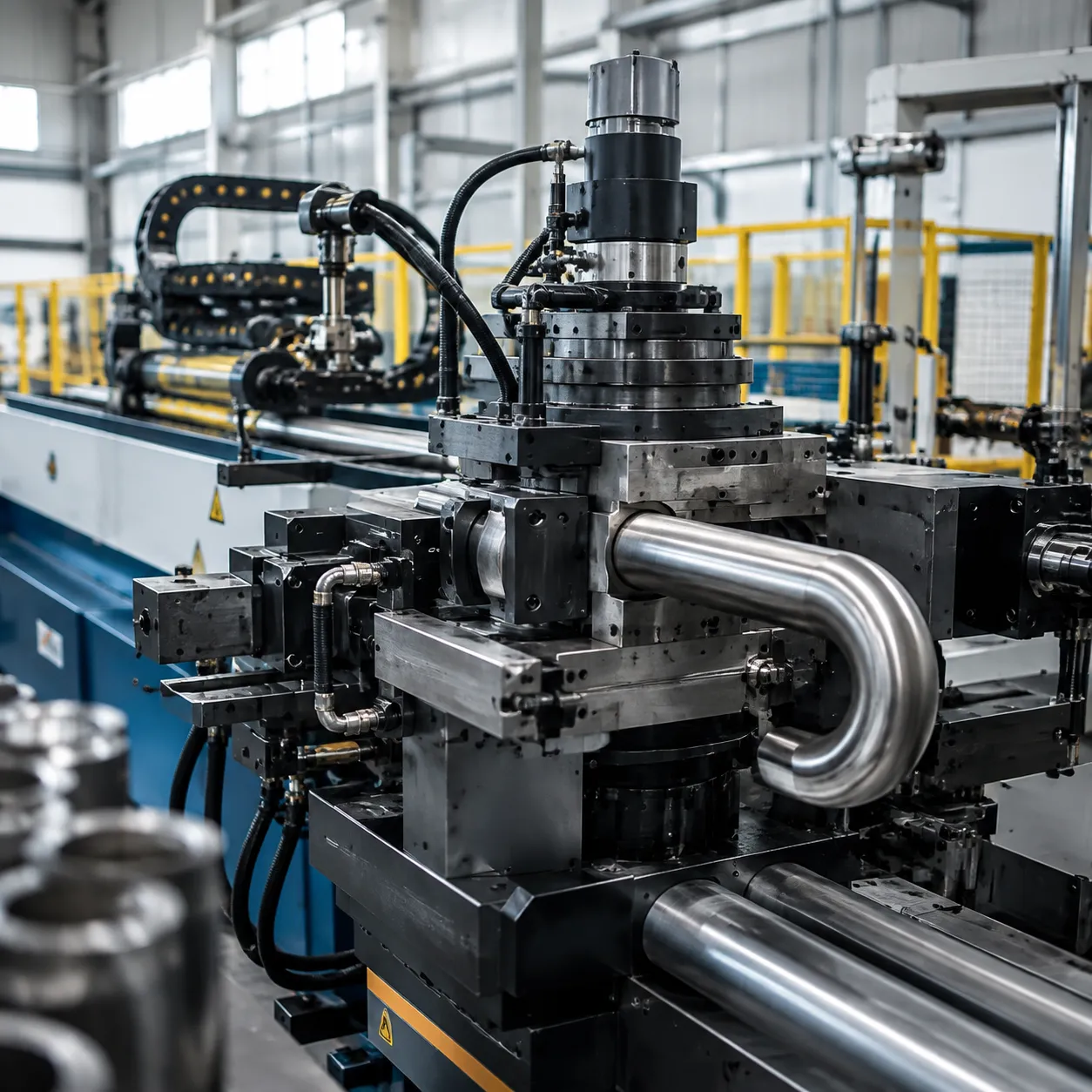
- Pipe bender control system: Two- and three-axis CNC pipe bender manuals cover MANUAL-1/MANUAL-2 and graphic programming modes parallel to press-brake controllers.
- Profile bending machine: Section-bending and profile bending machine PDFs document manual operating mode, angle presets, and wheel-axis setup for structural rolls.
- Steel bar bender: Rebar and steel bar bender operator PDFs add coil-feed and cut-length programming outside standard press-brake scope.
Field safety checks assume the controller scope and PDF revision listed in the applicable-series section.
Industrial Safety Protocols & Pre-Operation Checks
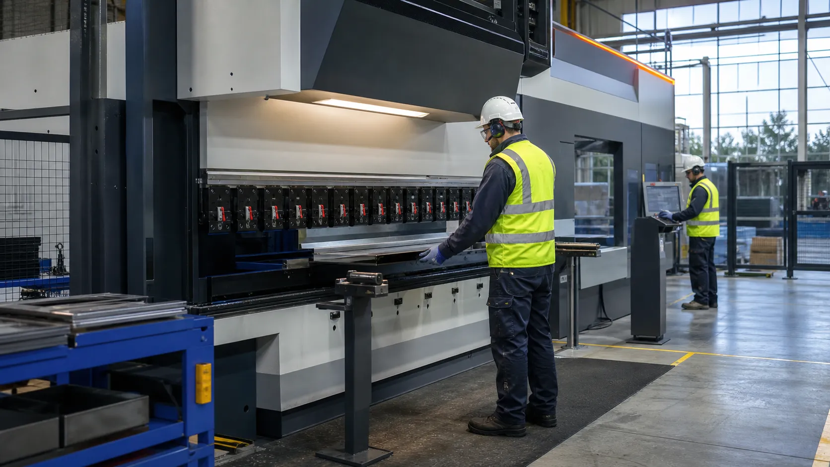
High-tonnage metal forming equipment requires daily review of safety operating procedures in the cnc bending machine manual pdf.
Mandatory PPE and Operator Training Standards
Every operator working near active bending machinery must wear certified protective gear and undergo strict operational training.
- Safety Glasses: Wear ANSI Z87.1-approved eyewear with side shields at all times.
- Footwear: Wear steel-toe work boots meeting ASTM F2413 standards to protect against falling sheet metal and heavy tooling.
- Hand Protection: Use ANSI Level A4 (or higher) cut-resistant gloves when handling sharp sheet metal edges and sharp punches.
- Apparel Rules: Prohibit loose clothing, neck chains, rings, and long un-tied hair near the ram or backgauge axes.
- Certified Training: Allow only trained personnel who have mastered the press brake user guide and controller setup to operate the machine.
E-Stop Systems and DSP Light Curtain Calibration
Your optical guarding system is your primary line of defense against severe pinch-point injuries. Test these systems before cycling the ram.
- E-Stop Verification: Press each Emergency Stop palm button—located on the main console, foot pedal, and controller panel—to confirm immediate power shutoff.
- Daily Light Curtain Test: Execute the optical beam test using the alignment test block specified in the cnc sheet bending machine pdf.
- DSP Guard Calibration: Verify that the DSP light curtain laser line aligns precisely with the tip of the upper punch.
- Muting Point Check: Confirm that the high-speed ram movement automatically switches to slow bending speed at 6 mm above the sheet surface.
CRITICAL SAFETY NOTE: Never bypass, bridge, or alter the optical sensor wiring. Operating a machine with an inactive light curtain instantly voids compliance and puts operators at extreme risk.
Lockout Tagout Procedures for Sheet Metal Machines
Perform this mandatory Lockout tagout procedures sheet metal machine sequence before changing tooling, clearing jams, or performing routine maintenance inside the hazard zone:
| Step | Action Item | Operational Procedure |
|---|---|---|
| 1 | System Shutdown | Lower the ram completely or park it securely on mechanical safety blocks. Turn off the controller. |
| 2 | Power Isolation | Switch the main electrical isolator handle on the cabinet door to the OFF position. |
| 3 | Lock & Tag Application | Attach a personal lockout padlock and a filled-out warning tag to the main breaker switch. |
| 4 | Pressure Relief | Bleed off remaining hydraulic line pressure using the manual relief valve. |
| 5 | Zero-Energy Test | Try to power on the machine to verify total electrical and hydraulic isolation before starting work. |
Pinch Points and Safety Block Placement
The throat depth, tooling area, and multi-axis backgauge are active danger zones. Manage these hazard areas with strict physical barriers and mechanical supports.
- Pinch Point Awareness: Keep hands entirely clear of the upper punch and lower V-die closing gap during operation. Use sheet supports for wide plates.
- Backgauge Hazards: Never reach behind the tooling area while the backgauge X, R, or Z axes are moving.
- Safety Block Insertion: Place certified mechanical safety blocks between the top ram and lower bed whenever you perform setup, maintenance, or cleaning inside the die area.
- Clear Work Zone: Keep the floor around the foot pedal clean and free of oil, metal chips, and scrap cutoffs to prevent accidental pedal presses.
Foundation leveling and power hookup precede controller boot and material-library setup.
Machine Delivery, Rigging & Installation Requirements
Correct rigging and foundation prep prevent structural twist on hydraulic bending machine installs.
Rigging and Lifting Heavy Machinery
Moving a heavy hydraulic bending machine requires certified rigging equipment matched to the total machine weight.
- Verify Rigging Points: Always lift using the dedicated overhead crane lifting holes or designated forklift channels marked on the frame. Never place straps around the backgauge axis, light curtains, or hydraulic cylinders.
- Weight Capacities: Check the shipping crate nameplate. Equipment weights range from 8,000 lbs (40-ton models) to over 90,000 lbs (1000-ton models). Ensure crane cables and shackles carry a minimum 1.5x safety factor rating.
- Uncrating: Remove protective plastic sheeting immediately upon arrival. Inspect all painted surfaces, linear guides, and control cabinets for moisture or transit damage before unbolting the frame from the transport skid.
Concrete Foundation and Leveling Specs
A stable foundation ensures long-term NC position controller accuracy and prevents frame flexing during full-tonnage bends.
| Parameter | Standard Machine (Up to 150T) | Heavy-Duty Machine (200T to 1000T+) |
|---|---|---|
| Concrete Thickness | Minimum 6 inches (150 mm) | Minimum 10–12 inches (250–300 mm) |
| Concrete Grade | 3,000 PSI reinforced | 4,000+ PSI mesh/rebar reinforced |
| Leveling Tolerance | 0.05 mm / 1000 mm (X and Y axes) | 0.02 mm / 1000 mm (X and Y axes) |
| Isolation | Anti-vibration rubber pad mounts | Dedicated isolated foundation pit |
- Use precision machinist levels on the bed surface. Adjust the leveling jack bolts underneath the bed frame until all four corners sit completely level before torquing anchor bolts.
Electrical Power Connection & Cabinet Wiring
Connect your power lines following national electrical codes and our press brake user guide schematics.
- Voltage Stability: Standard units require 480V AC, 3-phase, 60Hz (or 230V AC depending on model configuration). Voltage fluctuation must remain within ±5%. Install an external voltage stabilizer if grid power fluctuates beyond this margin.
- Grounding: Connect a dedicated copper grounding wire (minimum 10 AWG) directly to the main grounding busbar inside the electrical cabinet. Do not ground to shop water pipes or structural steel columns.
- Phase Alignment: Wire the main power leads (L1, L2, L3) to the main breaker disconnect. Turn on power briefly to check main motor rotation direction. If the hydraulic pump runs loud or fails to build pressure, swap any two supply phases immediately to correct motor rotation.
Hydraulic and Pneumatic Line Hookup
Complete fluid and air connection procedures before starting initial commissioning.
- Hydraulic System Priming: Fill the main reservoir with fresh, filtered ISO VG 46 (for standard ambient temperatures) or ISO VG 32 (for cold shop environments) hydraulic oil through a 10-micron filter cart. Bleed air from the high points on the Y1/Y2 hydraulic cylinders via the top bleed screws prior to full pressure operation.
- Pneumatic Clamping: Connect clean, dry compressed air to the quick-disconnect pneumatic inlet regulator. Set shop air line pressure between 6.0 to 8.0 bar (87 to 116 PSI) for pneumatic punch clamping systems and rear sheet support accessories.
Programmed angles depend on punch-and-die alignment and crowning compensation in the tooling section.
CNC Controller Setup & Operation Guide
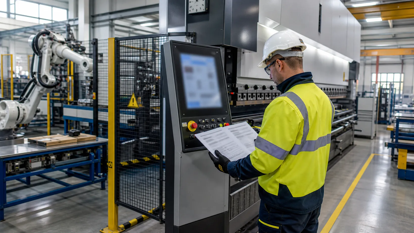
Programming workflows mirror how a CNC bending machine works for punch-and-die cycles before importing DXF or graphic programs.
Controller boot, material library, and program import steps follow the operation manual sequence for each Delem, ESA, or Cybelec interface.
System Booting & Axis Calibration
Power up the controller and complete the homing routine before initializing any operation manual routines:
- Power On: Switch on the main electrical cabinet breaker and start the CNC terminal.
- Safety Circuit Reset: Clear all E-stop buttons and reset the light curtain guard circuit.
- Axis Reference Calibration: Press the system Start button to initiate automated homing for the Y1, Y2, X, R, Z1, and Z2 axes.
- Zero Position Check: Verify physical axis position against display readouts on the graphic programming interface.
Material Library Configuration
Accurate material data prevents structural overload and off-angle bends in sheet metal fabrication:
- Sheet Thickness: Enter precise measured thickness using a caliper rather than nominal sheet gauge.
- Tensile & Yield Parameters: Input exact material values (e.g., Mild Steel at 420 MPa, Stainless at 650 MPa, Aluminum at 200 MPa).
- Grain Direction: Define bend orientation relative to rolling grain to optimize automatic springback calculations.
Programming Modes & CAD File Import
Controller programming instructions cover manual entry, graphic programming interface drawing, and DXF import paths.
Choose the appropriate entry mode based on production complexity:
| Programming Mode | Optimal Application | Setup Method |
|---|---|---|
| Numerical Direct Angle | Rapid single-bend runs & shop prototypes | Enter target angle, flange length, and V-die width. |
| 2D/3D Graphic Interface | Complex multi-bend structural profiles | Draw geometry directly on-screen with visual folding. |
| DXF File Import | Production runs from CAD systems | Load vector files via USB or network to auto-extract bend lines. |
Bend Sequencing & Collision Detection
Automated path calculation protects tooling and operator hardware:
- Automatic Sequence Optimization: The CNC controller evaluates part geometry and calculates the optimal bend sequence to minimize sheet flipping.
- 3D Collision Prevention: The software simulates stroke movement to flag potential collisions between sheet metal, upper punches, lower V-dies, and backgauge stops.
- Backgauge Speed Adjustment: Throttle backgauge drive speeds for large, thin sheet panels to prevent material shifting prior to full clamping.
Tooling wear and fluid condition tie directly to the service intervals in the maintenance chapter.
Punch & Die Setup, Crowning & Angle Adjustment
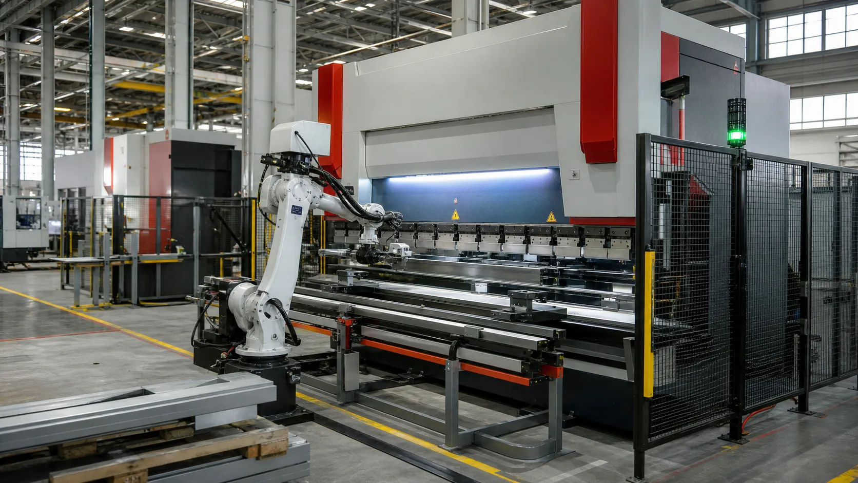
Precise bends require tool alignment, crowning, and the angle adjustment procedure in the tooling setup guide.
Tooling Selection: Promecam vs. Trumpf/Wila Clamping Systems
ProMach equips machines with flexible clamping interfaces to match shop tooling inventory:
| Feature | Promecam / European Style | Trumpf / Wila Style |
|---|---|---|
| Clamping Mechanism | Manual quick-clamp or bolt-tightened plates | Automated hydraulic or pneumatic pushbutton locking |
| Tool Loading | Side-loading or front snap-in | Vertical self-seating and self-aligning |
| Best Application | Standard job shop sheet metal fabrication | High-mix, fast setup industrial production |
Upper Punch and Lower V-Die Installation & Alignment
Follow this step-by-step press brake punch and die setup guide to align your tooling correctly before every production run:
- Clean Contact Surfaces: Wipe down the upper ram rail, die bed, and tool shanks to remove burrs, metal dust, and oil buildup.
- Mount Upper Punch: Insert punch segments into the upper clamping bar. Engage the safety groove pins and lock clamps lightly.
- Position Lower V-Die: Place the V-die block onto the lower bed rail, ensuring it seats flat.
- Center the Axis Alignment: Lower the ram in low-speed jog mode until the punch tip enters the lower V-groove.
- Torque Fasteners: Tighten upper clamps and lower bed locking screws starting from the center and working outward to equal torque specifications.
Mechanical Crowning Adjustment Press Brake Systems
Long bending operations cause natural ram flex, leading to shallow bend angles in the center of the sheet ("canoe effect"). Automated crowning addresses this issue using automated crowning compensation:
- Hydraulic Crowning: Uses hydraulic cylinders inside the lower bed to push upward, matching real-time bending tonnage.
- Mechanical Motorized Crowning: CNC-controlled anti-deflection wedges slide horizontally to create an upward parabolic curve along the bed length.
- Automatic CNC Calculation: The controller automatically adjusts crowning based on sheet thickness, material yield strength, and bend length entered in the program.
Press Brake Springback Compensation & Angle Correction
Different metal grades react differently when released from pressure. Follow this direct angle adjustment procedure to maintain precision across your entire batch:
Critical Safety Note: Always calculate springback using test pieces of the exact material batch before running full production runs.
- Springback Factor: Material springback increases with higher tensile strength, larger inner bend radii, and thinner sheet stock.
- Basic Springback Compensation Logic: Corrected Angle = Target Angle - Springback Angle
- Executing CNC Angle Correction:
- Perform a trial bend on scrap stock of your target material.
- Measure the resulting angle with a calibrated digital protractor.
- Enter the measured angle directly into your CNC controller's angle correction screen.
- The controller recalculates Y1/Y2 stroke depth automatically to hit the exact angle on the next bend.
When scheduled service does not clear a fault, use the alarm tables in the diagnostic section.
Routine Service Protocols & Equipment Longevity Guide
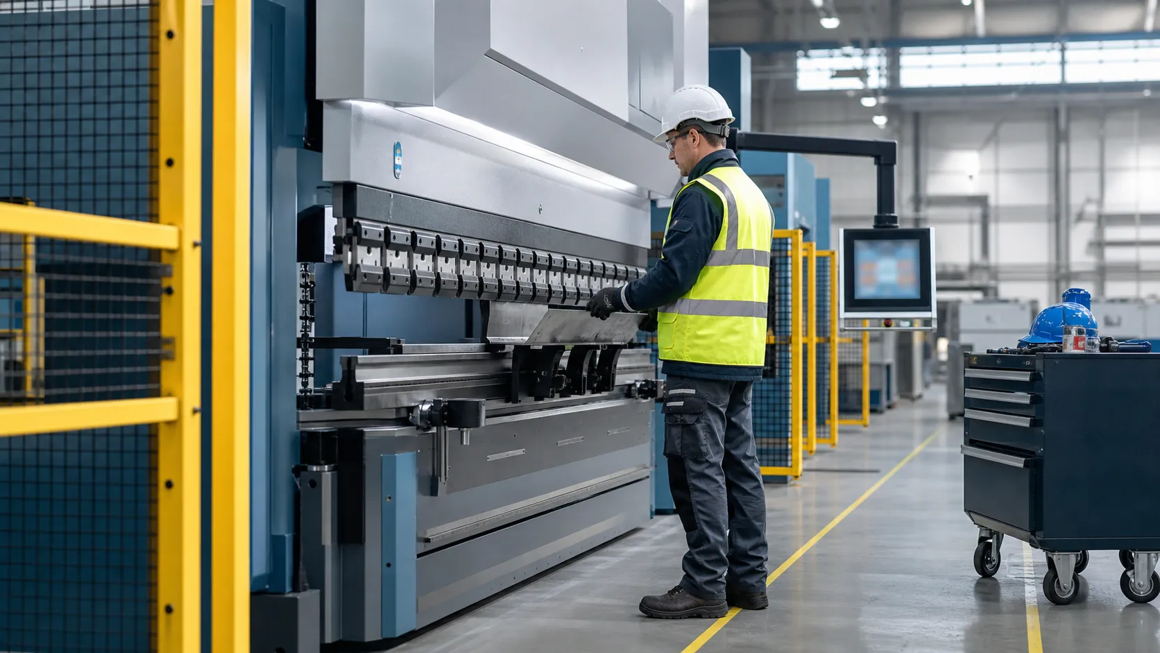
Disciplined maintenance instructions in the PDF protect micron-level repeatability on production shifts.
CRITICAL SAFETY NOTICE: Always engage Lockout/Tagout (LOTO) protocols and position mechanical safety blocks under the ram before performing any maintenance, lubrication, or cleaning inside the die area.
Daily Checkpoints for Operational Readiness
Start every shift with a quick 5-minute inspection before powering up the controller and running sheet metal parts:
- Hydraulic Oil Level: Check the reservoir sight glass. Oil levels must remain between the middle and upper gauge marks.
- System Pressure Check: Monitor system gauges upon startup to verify working pressure stabilizes within factory parameters.
- Emergency Stop & Safety Tests: Test all E-stop buttons, foot pedal switches, and safety light curtains for immediate axis motion interruption.
- Tooling Cleanliness: Clean punch tips, V-die slots, and clamping assemblies. Wipe away mill scale, rust, and debris to prevent tooling wear and inaccurate bend angles.
Weekly and Monthly Maintenance Schedules
Regular lubrication and filtration checks prevent wear on high-precision backgauge components and hydraulic control valves.
| Frequency | Target Component | Maintenance Action | Lubricant / Spec |
|---|---|---|---|
| Weekly | Linear Guide Rails | Clean guide tracks and apply fresh grease along X, R, and Z axes | Lithium Base Grease (NLGI Grade 2) |
| Weekly | Hydraulic Lines & Fittings | Inspect all hose connections for fluid weeping or jacket abrasion | N/A (Tighten or replace fittings) |
| Monthly | Backgauge Ball Screws | Degrease drive screws, check for backlash, and repack ball nuts | ISO VG 68 Slideway Oil / Lithium Grease |
| Monthly | Electrical Cabinet & Air Filters | Clean air intake fan filters; check hydraulic return filter indicators | Compressed air blowdown / Replace cartridge |
Annual System Servicing & Calibration
Perform an in-depth annual service to restore factory precision and prevent component fatigue:
- Hydraulic Oil Replacement: Flush and drain the reservoir completely. Clean the magnetic drain plug and refill with fresh fluid meeting hydraulic oil ISO VG 46 specifications (or VG 32 for cold climate facilities).
- Proportional Valve Calibration: Recalibrate Y1 and Y2 proportional valves using the press brake user guide procedure to ensure precise ram synchronization across full stroke length.
- Structural Bolt Torque Inspection: Check high-tensile frame assembly bolts, cylinder mounting hardware, and backgauge mounts with a calibrated torque wrench to ensure structural rigidity.
Recommended Spare Parts Inventory
Keep these essential replacement parts stocked in your plant maintenance room to resolve wear-and-tear issues immediately:
- Hydraulic Seals & O-Rings: High-pressure cylinder piston seal kits, gland packing sets, and valve manifold seals.
- Filter Elements: Return line oil filter cartridges, breather caps, and enclosure intake filter pads.
- Electrical Components: Backgauge proximity switches, 24V DC control relays, foot switch cables, and spare fuse packs.
- Tool Clamping Hardware: Quick-clamp spring pins, sectional wedge adjustment screws, and precision shims.
CNC Bending Machine Manual PDF: Diagnostic Guide for Common Faults
Unexpected downtime on a hydraulic bending machine starts with axis, hydraulic, and controller alarm checks in this diagnostic chapter.
Fixing Axis Positioning Errors and Y1/Y2 Synchronization Failure
- Axis Jitter and Inaccurate Bending Angles: Clean the glass optical encoders on both side frames using an alcohol wipe. Dust buildup distorts position feedback.
- Y1/Y2 Synchronization Failure: Inspect proportional valve amplifier cards for loose wiring. Recalibrate the reference points directly through the CNC controller interface.
- Backgauge Axis Positioning Errors: Check the X-axis and R-axis ball screws for debris. Wipe clean, apply fresh grease, and verify mechanical zero points.
Hydraulic Overheating, Pressure Drops, and System Noise
- Hydraulic System Overheating (Above 60°C / 140°F): Check the oil cooler fan power supply and clean clogged heat exchanger fins. High heat breaks down ISO VG 46 hydraulic oil and damages internal seals.
- Sudden Pressure Drop: Inspect the main proportional pressure valve for trapped metal shavings. Flush the valve body, inspect the internal O-rings, and verify pump pressure thresholds.
- Excessive Pump Cavitation Noise: Check the hydraulic oil level sight glass immediately. Top off the reservoir and inspect the suction filter element for clogging.
Delem Controller Alarm Codes and Corrective Actions
| System Alarm Code | Suspected Root Cause | Immediate Corrective Action |
|---|---|---|
| E-2010 (Sync Fault) | Y1/Y2 scale position mismatch exceeds tolerance limit. | Clean optical encoders, check proportional valve feedback, and rerun axis homing. |
| A-4022 (Pressure Timeout) | Target pressure not reached within preset time. | Check main pump relay, inspect hydraulic oil level, and clean main pressure valve. |
| E-1050 (Axis Limit) | Backgauge X-axis hit hardware or software limit switch. | Manually jog axis back into safe zone; check material thickness inputs. |
| E-3001 (Emergency Stop) | E-stop button depressed or light curtain beam broken. | Reset E-stop circuit; align DSP light curtain transmitter and receiver units. |
Electrical Cabinet Fault Isolation: Inverters and I/O Signals
- Frequency Inverter Error Inspection: Read the diagnostic code on the drive display. Verify that incoming 3-phase line voltage matches cabinet ratings and check for motor ground faults.
- I/O Board Signal Diagnostics: Trace 24V DC control signal loops using a digital multimeter. Verify that input LEDs illuminate on the controller I/O modules when limit switches activate.
- Loose Terminal Verification: Perform a physical tug-test on all terminal block connections every 500 operating hours to prevent intermittent signal drops caused by machine vibration.
ProMach CNC Bending Machine Technical Specifications
ProMach metal forming equipment to meet strict export shop tolerances and production demands. Below is the detailed technical breakdown for our line of CNC sheet bending machines, matching the baseline parameters in our official cnc bending machine manual pdf.
Drive System Comparison: Electro-Hydraulic Servo vs. Full Electric Servo
Two main drive platforms to match your shop's speed, energy, and force requirements:
| Parameter | Electro-Hydraulic Servo Press Brake | Full Electric Servo Press Brake |
|---|---|---|
| Power Source | Hybrid Servo Motor + Hydraulic Pump | Direct-Drive Electric Servo Motor & Belt System |
| Tonnage Range | 100 Ton to 1000 Ton+ | 40 Ton to 150 Ton |
| Energy Consumption | Low (Motor idles when ram stops) | Ultra-Low (40%–60% savings over standard hydraulics) |
| Positioning Accuracy | ±0.01 mm | ±0.005 mm |
| Fluid Maintenance | Required (ISO VG 46 / VG 32) | Zero Hydraulic Oil Needed |
Machine Capacity Matrix
Our standard machine capacity matrix covers light precision sheet work up to heavy structural fabrication:
- Tonnage Range: 40 Tons to 1000+ Tons
- Bending Length: 1,500 mm to 6,100 mm (5 ft to 20 ft)
- Throat Depth: 320 mm to 500 mm standard (custom deep throat options available)
- Daylight Opening (Open Height): 400 mm to 650 mm
- Stroke Length: 150 mm to 350 mm
Multi-Axis Backgauge Configurations & Crowning Systems
Precision bending requires exact sheet positioning and real-time deflection compensation. ProMach equips machines with up to 6-axis CNC backgauges alongside dynamic crowning systems:
- Y1 / Y2 Axes: Independent electro-hydraulic closed-loop servo control for ram leveling and taper bending.
- X Axis: High-speed ball screw drive for precise backgauge depth positioning.
- R Axis: Automatic CNC vertical backgauge finger height adjustment.
- Z1 / Z2 Axes: Independent left/right lateral motion for multi-station bending.
- Crowning Systems: Automated mechanical crowning adjustment or hydraulic auto-compensation to eliminate center-line deflection and hold uniform angles across the full bending length.
Hydraulic System Parameters
To ensure thermal stability and peak system pressure, follow these exact fluid specifications outlined in our hydraulic bending machine user guide:
- System Pressure Threshold: Rated for maximum continuous operating pressure up to 315 Bar (4,560 PSI).
- Reservoir Capacity: Ranges from 120 Liters (31 Gal) on 100T models up to 800+ Liters (211 Gal) on high-tonnage units.
- Hydraulic Oil ISO VG 46 Specifications: Use high-grade anti-wear ISO VG 46 hydraulic oil for standard ambient shop temperatures (50°F to 104°F / 10°C to 40°C).
- Hydraulic Oil ISO VG 32 Specifications: Use ISO VG 32 for cold or unheated shop environments consistently operating below 50°F (10°C).
ProMach Global Support, Spare Parts & Customization
Automated lines documented in the automatic CNC bending machine brochure share the same controller PDF revision paths.
Are machine downtime, missing components, or complex bending jobs slowing down the shop floor? ProMach backs every ProMach machine with factory-direct technical support, rapid replacement parts, and custom engineering to keep your sheet metal fabrication operating at peak efficiency.
Remote Diagnostics Beyond Your CNC Bending Machine Manual PDF
When field issues extend beyond standard troubleshooting steps in the cnc bending machine manual pdf, our tele-service engineers step in. Tele-service teams connect directly to your Delem, ESA, or ProMach SmartCNC controller via secure network connections to resolve system faults in real time.
- Live Parameter Tuning: Remote adjustment of axis calibration, crowning parameters, and hydraulic valve timing.
- PLC I/O Signal Tracing: Direct identification of faulty sensors, cabinet wiring faults, or drive alarms.
- Firmware Updates: Remote installation of controller patches and updated material springback libraries.
Genuine Parts Ordering & Rapid Dispatch
ProMach maintains a regional spare-parts inventory for instant dispatch of genuine ProMach replacement parts. Order standard components directly to minimize operational downtime.
| Component Category | Included OEM Parts | Dispatch Lead Time |
|---|---|---|
| Hydraulic Components | Valve blocks, oil filter elements, main seals, pump units | Same-day / 24 Hours |
| Electrical & Controls | Relay switches, proximity sensors, servo drives, I/O boards | Same-day / 24 Hours |
| Safety Systems | DSP/Lazersafe light curtain optical units, E-Stop buttons | 24 Hours |
| Tooling & Mechanical | Hardened punches/dies, ball screws, linear guide blocks | 24 - 48 Hours |
Custom OEM/ODM Bending Solutions
Standard machine configurations do not always fit specialized production lines. OEM scopes design and build engineered-to-order hydraulic bending machine systems tailored to your specific application requirements.
- Tailored Frame Geometry: Custom press brakes ranging from 40T to over 1000T with extended stroke lengths, deeper throat depths, and enlarged daylight openings.
- Robotic Automation Integration: Turn-key robotic bending cells equipped with automated sheet loaders, magnetic grippers, and 6-axis robot arms.
- Specialized Tooling Packages: Custom multi-V lower dies, heavy-duty radius punches, and pneumatic quick-clamping systems.
Factory PDF packages cover controller type, tonnage class, and voltage map for cnc bending machine pdf commissioning—contact ProMach with machine model and Delem/ESA/Cybelec controller ID for the latest revision bundle.